
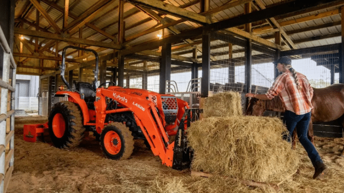
Kubota L4470 Tractor Maintenance, Parts and Repair Guide
Kubota L4470 tractor maintenance starts with the correct service schedule, clean fluids and filters, and regular checks of the cooling system, steering, brakes and safety controls. This guide explains the documented maintenance requirements, how to identify replacement parts, and practical checks for difficult starting, reduced power, overheating and electronic warnings.
The L4470 belongs to the Grand L70 Premium range. Open-station and cab configurations require different parts in some assemblies, while loaders and other attachments have their own identification and maintenance requirements. Order against the complete tractor model and serial number rather than the L4470 name alone.trochumotors+1
L4470 Tractor Maintenance
Before servicing, park on firm, level ground, set the parking brake, lower all implements, place the transmission range selector in neutral, stop the engine and remove the key. Disengage the PTO and wait for moving components to stop. Allow the engine, exhaust and cooling system to cool before working nearby.
Kubota instructs owners to disconnect the battery ground cable before working on or near electrical components. Disconnect the negative cable first and reconnect it last. Never work beneath a loader or other equipment supported only by hydraulic pressure; use the specified mechanical support or suitable stands and blocking.manua+1
Maintenance Schedule and Service Points
The following selected service points come from the operator’s manual covering the L3770, L3970, L4270, L4470, L5070 and L6070. They do not replace its complete maintenance chart. Biodiesel use and dusty operating conditions can change certain requirements.manua+1
| Maintenance task | Verified interval or trigger | Specification or inspection point | Owner action |
|---|---|---|---|
| Initial engine oil and filter service | First 50 operating hours | Both oil and engine oil filter require attention | Change the oil and replace the filter using the applicable procedure |
| Initial transmission and hydraulic filter service | First 50 operating hours | Transmission oil filter and hydraulic oil filter are separate service items | Identify and replace both specified filters; do not assume this also requires the scheduled transmission oil change |
| Tractor greasing | Every 50 hours | Use the model-specific lubrication diagram | Clean fittings and lubricate the designated points |
| Starting and operator-presence systems | Every 50 hours | Check safety-system operation | Perform the manual’s functional tests without bypassing switches |
| Wheel bolt torque and tie-rod dust covers | Every 50 hours | Correct torque and intact protective covers | Check against the wheel configuration and inspect covers for damage |
| Primary air-cleaner element | Every 100 hours; more often in dust | Clean using the specified method | Inspect the element and sealing surfaces during service |
| Fan belt, brakes and battery condition | Every 100 hours | Belt adjustment, brake adjustment and battery condition | Follow the individual procedures and adjustment limits |
| Cab air filters and air-conditioning belt | Every 200 hours, cab models | Inner filter, fresh-air filter and belt tension | Clean filters and inspect or adjust the belt as instructed |
| Engine oil after initial service | Every 400 hours or one year, whichever comes first | Correct oil classification and temperature-dependent viscosity | Change the oil and record hours and date |
| Engine oil filter after initial service | Every 400 hours | Correct engine filter | Replace at the documented interval |
| Transmission oil, transmission filter and hydraulic filter | Every 400 hours after initial filter service | Fluid and filters are distinct maintenance items | Follow the draining, replacement and level-checking procedures |
| Front axle case oil | Every 400 hours | Separate from transmission oil | Drain and refill according to the axle procedure |
| Air-cleaner primary and secondary elements | Every 1,000 hours or one year, whichever comes first | Both elements are scheduled replacement items | Replace the correct elements; do not treat the secondary element as a routinely washable filter |
These intervals are manufacturer-documented. A leak, damaged hose, broken guard or abnormal operating condition requires attention when discovered rather than at the next scheduled service.manua+1
Lubrication and Fluid Requirements
Engine oil
The applicable manual specifies API CJ-4 engine oil for the DPF-equipped engine and lists viscosity choices according to ambient temperature. For temperatures below 14°F, or −10°C, its listed choices are SAE 10W-30 or SAE 0W-40. Select the oil from the complete temperature chart and confirm the suitability of any current replacement product with Kubota.manua
Do not select oil solely because it is labelled “diesel engine oil.” The classification, viscosity and compatibility with the exhaust aftertreatment system all matter.
Transmission and hydraulic oil
The manual specifies Kubota SUPER UDT-2 fluid for the transmission case. The L4470 uses an electronically controlled hydrostatic transmission, so a generic hydraulic oil description is not an adequate substitute for the required fluid specification. Kubota notes that genuine fluid product names may differ between countries.manua+1
Keep the filling area clean and use the prescribed level-checking method. When investigating low oil, find the reason for the loss rather than repeatedly topping up.
Front axle oil
The front axle has its own oil service requirement. The manual lists Kubota SUPER UDT-2 fluid or SAE 80–SAE 90 gear oil for this assembly. This alternative does not mean that gear oil is acceptable in the transmission. Confirm the product and filling procedure for the axle before servicing it.manua
Grease points
The lubrication table specifies multipurpose NLGI-2 or NLGI-1 grease, with the GC-LB designation. Listed locations include front axle supports, the top link, lift rod and lift-cylinder pivots, with model-dependent differences in the lubrication diagram.manua
Use the diagram to identify actual fittings. Do not assume that every bearing is greaseable, and do not add the loader’s grease points to the tractor schedule without checking the loader manual.
Wear Checks That Can Reveal Repair Needs
Use maintenance access to look for developing faults. The following are general inspection checks, not permission to dismantle or adjust an assembly without its service procedure:
-
Look for wet areas around hose crimps, axle seals, filters and cylinder rods. Clean the area safely so the origin can be distinguished from oil running down from elsewhere.
-
Inspect the fan belt for damaged edges, cracks and contamination. A replacement belt will not correct a damaged pulley or persistent misalignment.
-
Check tie-rod dust covers for splits or displacement. A damaged cover needs attention before dirt and water contaminate the joint.
-
Examine air-cleaner seals and intake connections. Dirt downstream of the filter warrants investigation before further operation.
-
Inspect battery cables for loose terminals, corrosion and damaged insulation.
-
Look for damaged wiring near moving controls, brackets and attachment mounting points.
Kubota specifically schedules tie-rod dust-cover inspection and identifies cracked, hardened, deformed or otherwise damaged hoses as replacement conditions. Its manual directs several hose-replacement operations to a dealer.manua+2
Preseason Preparation and Storage
Before a busy season, reconcile the hour meter with the service record. Check fluid levels, belt condition, battery condition and tire pressures for the fitted tires. Test the starting and operator-presence systems using the manual’s procedure.
For extended storage, Kubota’s instructions include changing the engine oil, running the engine for about five minutes to circulate it, lubricating exposed areas that may rust, lowering implements, protecting exposed hydraulic-cylinder rods and removing the battery for appropriate storage. Keep the PTO disengaged and store the tractor in a dry, sheltered location. Let the engine and exhaust cool before covering it.manua
When returning the tractor to service, check fluids, tire pressures, battery charge and belt tension. After starting in a safely ventilated location, monitor the gauges, inspect for leaks after shutdown and verify brake operation before normal work.manua
Finding wear is only the first step. The replacement must match the affected assembly, tractor configuration and any applicable serial-number qualification.
Finding the Correct L4470 Replacement Parts
Model, Serial Number and Configuration Checks
Prepare the following information before ordering:
-
Complete tractor model designation from its identification plate.
-
Tractor serial number.
-
Engine identification when ordering engine-related components.
-
Open-station or cab configuration.
-
Installed options relevant to the part, such as rear hydraulic remotes.
-
Separate model and serial details for the loader or other attachment.
-
Photographs of the component, its connections and any readable markings.
Kubota identifies the US Premium model as L4470PRM and also lists cold-weather cab configurations with additional equipment. Dealer catalogs may separate the tractor and cab versions, so select the matching configuration before choosing an assembly.kubotausa+1
Do not assume that every L4470 component is identical throughout production. Have the dealer check the serial-number applicability and any supersession before ordering. No specific serial-number break is established here.
Parts Diagrams and Manuals
The English US operator’s manual identified by code TD540-1971-1 includes the L4470 alongside five other L70 models. Its shared cover does not make every capacity, illustration or instruction universal: use the L4470 and Premium-model qualifications within the manual.manua
Use three different kinds of information for different jobs:
-
The operator’s manual explains maintenance, operation and owner checks.
-
The illustrated parts catalog identifies assemblies and replacement components.
-
Applicable workshop information supplies repair procedures, measurements and adjustments beyond routine maintenance.
Messick’s provides a dedicated L4470 parts catalog, while Coleman Equipment identifies the L4470 Premium Grand L in its parts system. Start with the relevant assembly rather than a general list of frequently purchased items.messicks+1
When reading a diagram:
-
A reference number identifies the component’s position in the drawing; it is not necessarily an orderable number.
-
The part number identifies the item to order.
-
A superseded number requires confirmation of the current replacement and any installation qualifications.
-
An assembly listing may contain several components, but its contents should be checked rather than assumed.
Replacement Parts and Fitment Checks
Part numbers are omitted below where an exact, configuration-qualified number has not been established. The identification details are more useful than an unsupported number.
| Component | Verified part number, if available | Fitment qualification | What to check before ordering |
|---|---|---|---|
| Engine oil filter | Not specified here | Match the L4470 engine application | Confirm the current filter number against the tractor and engine details |
| Transmission oil filter | Not specified here | Distinct from the hydraulic oil filter | Identify its location and diagram description before ordering |
| Hydraulic oil filter | Not specified here | Separate scheduled filter service item | Confirm that a service kit includes this filter as well as the transmission filter |
| Primary and secondary air-cleaner elements | Not specified here | Two separate elements | Order the required element or both scheduled replacements; check housing identification |
| Fuel filter | Not specified here | Match the tractor’s fuel-system assembly | Distinguish the replaceable filter from water-separator components |
| Fan belt | Not specified here | Match the engine accessory drive | Check the diagram, pulley arrangement and current replacement number |
| Cab air filters | Not specified here | Cab models only | Distinguish inner recirculation and fresh-air filters |
| Hydraulic hoses | Not specified here | Match the exact circuit and installed equipment | Confirm routing, end connections, pressure specification and any dealer-service requirement |
The maintenance chart confirms these separate filter and belt applications. It does not establish interchangeability with older Grand L models or other L70 tractors.manua
Critical Hardware and Attachment Parts
Do not order attachment hardware from the tractor model alone. A loader mounting fastener, implement PTO guard and snowblower shear bolt belong to different assemblies and may require separate catalogs.
For wheel and mounting hardware, match the original application and use the specified tightening procedure. Do not substitute a visually similar bolt where its strength, length or locking arrangement has not been confirmed.
Parts Sources in the USA and Canada
In the USA, an authorized Kubota dealer can check the tractor serial number, current part numbers and applicable service information. Messick’s and Coleman Equipment also provide model-specific L4470 catalog resources that can help identify the affected assembly.messicks+1
In Canada, use a Kubota dealer to confirm the Canadian configuration and locally supplied fluids. Trochu Motors lists the L4470 within its L70 range and provides access to the series operator’s manual.trochumotors
Before approving an order, confirm the part number, quantity, included seals or fittings, currency and total delivered cost. A catalog listing alone does not establish stock or delivery availability.
L4470 Tractor Problems and Repairs
The engine symptoms below appear in the operator’s manual that includes the L4470. They are troubleshooting categories, not evidence of widespread defects. Electronic warnings require separate attention because the tractor also monitors engine and vehicle-control systems.manua+1
Troubleshooting at a Glance
| Symptom | Plausible causes supported by the evidence | First safe check | Repair direction or escalation |
|---|---|---|---|
| Engine cranks slowly or is difficult to start | Weak battery, poor battery connections or unsuitable cold-weather oil viscosity | Inspect battery connections and review oil selection | Correct confirmed connection or battery faults; investigate persistent slow cranking |
| Engine cranks but will not start | No fuel flow, air or water in the fuel system | Check fuel quantity and visible fuel-system condition | Service a confirmed restriction or follow the documented bleeding procedure |
| Engine lacks power | Insufficient or dirty fuel; restricted air cleaner | Check fuel condition and air-cleaner service history | Correct confirmed fuel or intake problems before considering major engine work |
| Engine overheats | Excessive load, low coolant, fan-belt fault or blocked radiator/screens | Stop work and inspect only after safe shutdown and cooling | Remove confirmed obstruction or repair the identified cooling fault |
| Black exhaust smoke | Poor fuel, excessive engine oil or restricted air cleaner | Check oil level and air-cleaner condition | Correct the confirmed condition; seek service if smoke persists |
| Electronic warning or red STOP indication | A monitored engine or vehicle-control abnormality | Record the message, controller identification and complete code | Follow the applicable manual entry; stop immediately for a red STOP indication |
These are starting points for diagnosis, not instructions to replace a component based on the symptom alone.manua+1
Engine Cranks Slowly or Is Difficult to Start
Separate slow cranking from normal-speed cranking without combustion. Kubota’s troubleshooting table identifies a weak battery and increased oil viscosity in winter as possible starting difficulties. It also directs attention to battery cables and terminals.manua
With the engine stopped and key removed, inspect the battery connections and visible cable condition. Follow the electrical isolation procedure before cleaning or removing connections. Check that the engine oil viscosity is appropriate for the ambient temperature.
If inspection confirms a poor connection, correct it and reassess starting. If battery testing confirms inadequate capacity, charge or replace the battery as appropriate. Persistent slow cranking after those checks requires testing of the starting circuit and starter rather than repeated battery replacement.
Do not bridge starter terminals or bypass safety controls.
Engine Cranks Normally but Will Not Start
The manufacturer’s troubleshooting table identifies restricted fuel supply and air or water in the fuel system as possible causes. Start with fuel quantity and recent events: running out of fuel, fuel-filter work and contaminated fuel can help direct the investigation.manua
Safe initial checks include looking for external leakage, checking accessible fuel connections without disturbing them, and reviewing filter service history.
If inspection confirms a blocked filter, replace the correct filter and follow the applicable bleeding procedure. Do not apply older mechanical-diesel bleeding methods to this common-rail engine. Injector and high-pressure fuel-system diagnosis belongs with a suitably equipped technician.
Seek service if starting remains unsuccessful, a warning code appears, or fuel contamination may have reached injection components.
Engine Loses Power Under Load
Kubota identifies insufficient or dirty fuel and a clogged air cleaner as possible causes of reduced engine power. That makes intake and fuel checks appropriate before assuming turbocharger, injector or internal-engine failure.manua
Inspect the primary air-cleaner element and housing using the manual’s service method. Check whether the filter is overdue, damaged or incorrectly seated. Review the fuel supply and whether the symptom began after refuelling.
If inspection confirms a restricted air filter, service or replace the appropriate element. If fuel contamination is confirmed, address the contaminated supply rather than installing filters repeatedly without correcting the cause.
Stop and seek diagnosis if power loss remains after basic checks, particularly when accompanied by abnormal noise, persistent smoke or electronic warnings.
Engine Temperature Rises Under Load
The operator’s manual lists excessive load, low coolant, a loose or damaged fan belt, dirty radiator or grille screens, and restricted coolant circulation as possible overheating causes.manua
Stop working when the temperature becomes abnormal. Follow the manual’s warning response, then allow safe cooling before opening the hood or examining the cooling system. Never remove a hot radiator cap.manua
With the tractor shut down and cool:
-
Inspect the grille screens and radiator area for debris.
-
Check the coolant recovery-tank level.
-
Look for visible leakage around hoses and connections.
-
Inspect the fan belt for damage.
-
Consider whether the operating load or transmission range was inappropriate.
If inspection confirms debris obstruction, clean it using the specified method. If a belt is damaged, replace it and check the associated pulleys. Repeated coolant loss or overheating after these corrections requires further cooling-system diagnosis, not continued operation with frequent top-ups.
Black Exhaust Smoke
The manual identifies poor fuel quality, excessive engine oil and a clogged air cleaner as possible causes of black smoke. It does not establish any one of these as the cause on an individual tractor.manua
After safe shutdown, check the oil level by the prescribed method and inspect the air cleaner. Note whether the smoke began after an oil change or refuelling.
If overfilling is confirmed, correct the oil level before further operation. If the intake is restricted, service the filter correctly. Persistent smoke, especially with power loss or warning messages, requires diagnosis of the engine and related systems.
Do not alter fuel settings or emissions components in an attempt to suppress smoke.
Electronic Warnings and Unexpected Control Behavior
The instrument display can identify the affected controller, a trouble message and an error or warning code. Kubota distinguishes the ECU, or engine control unit, from the VCU, or vehicle control unit. Codes use SPN and FMI information together.manua
Before dismissing a message, record:
-
The complete displayed code.
-
The controller abbreviation.
-
The wording of the message.
-
The warning symbol and colour.
-
Whether the fault occurred during starting, travel, PTO operation or attachment use.
A red STOP symbol indicates a serious fault requiring an immediate stop and corrective action. A yellow alert identifies an abnormal condition requiring prompt attention. Dismissing a message with the back button does not repair the fault.manua
For unexpected travel response, stop using the tractor until the cause is understood. A sensor-related code does not by itself prove the sensor needs replacement; wiring, connections and the associated mechanism may require testing. Follow the matching manual entry and refer unlisted codes to an authorized dealer.
Owner Maintenance or Professional Repair?
Owner maintenance is appropriate when the applicable manual provides the procedure and the owner has the required tools, access and ability to complete it safely. Examples include documented fluid checks, lubrication, filter service, screen cleaning and visual inspections.
Professional service is appropriate for work involving:
-
Common-rail injection components.
-
Persistent engine or vehicle-controller faults.
-
Internal hydrostatic transmission repairs.
-
Unexplained coolant loss or repeated overheating.
-
Steering, braking or structural damage.
-
Cab refrigerant handling.
-
Repairs requiring pressure measurements, calibration or specialist support equipment.
Kubota specifically directs owners to a dealer for several tasks, including replacement of power-steering hoses, oil-cooler lines, lift-cylinder hoses and cab air-conditioning hoses. Its service chart also assigns engine valve-clearance adjustment to dealer service.manua+2
Before authorizing a major repair, obtain a confirmed diagnosis, the proposed parts list and a written labour estimate. For attachment-related damage, establish whether the fault is in the tractor, mounting system or attachment before approving disassembly.
Frequently Asked Questions
Which operator’s manual includes the L4470?
The English US manual identified by code TD540-1971-1 includes the L3770, L3970, L4270, L4470, L5070 and L6070. Confirm that its edition and market match the tractor, and follow the model-specific qualifications inside it.manua
Is the first 50-hour service just an engine oil change?
No. The maintenance chart also includes the engine oil filter, transmission oil filter and hydraulic oil filter at the initial 50-hour service. The initial filter requirements should not be confused with the later scheduled transmission oil change.manua+1
Can the same oil be used in the transmission and front axle?
The manual lists Kubota SUPER UDT-2 for the transmission and allows that fluid or SAE 80–SAE 90 gear oil in the front axle. The axle’s gear-oil option does not apply to the transmission.manua
Does biodiesel change maintenance requirements?
It can. Kubota permits qualifying biodiesel blends under specified conditions and provides additional fuel-handling and maintenance requirements. Before changing to a higher biodiesel concentration, read that section rather than assuming the standard service chart remains unchanged.manua+1
Troubleshoot starting issues
For your Kubota L4470, first establish whether the engine does not crank, cranks slowly, or cranks normally but will not start. Those symptoms lead to different checks. Kubota’s troubleshooting table identifies weak battery power, cold-weather oil viscosity, restricted fuel flow, and air or water in the fuel system as possible starting causes—not automatic diagnoses.manua
1. If the engine does not crank
This means the starter does not turn the engine, whether you hear silence or a click.
Begin with the normal starting setup: sit in the operator’s seat, apply the parking brake, disengage the PTO and place the controls in their prescribed starting positions. Use the L4470’s starting instructions rather than instructions for another Kubota model. Never bridge starter terminals or bypass a safety switch.
Then make these basic checks:
-
Turn the key on and note whether the instrument display illuminates.
-
Record any warning message before switching off.
-
With the key removed, inspect the battery terminals and visible cables for looseness, corrosion or damage.
-
Have the battery charged and load-tested if its condition is uncertain.
Kubota specifically recommends cleaning battery cables and terminals and charging the battery when insufficient battery power prevents adequate engine rotation. If a sound battery and clean connections do not restore cranking, the starting circuit needs testing rather than speculative replacement of the starter or ignition switch.manua
2. If the engine cranks slowly
A sluggish “rrr…rrr…” directs attention first to battery condition, connections and cold-weather starting conditions.
-
Check battery charge and terminal condition.
-
Review whether the engine oil viscosity suits the outside temperature.
-
Note whether the problem occurs only when cold or also with a warm engine.
Kubota identifies increased oil viscosity in winter as a possible cause of slow engine rotation and lists an optional engine block heater as a cold-start aid. Use only the oil choices and heater installation applicable to your tractor.manua
If it still turns slowly after a confirmed good battery and connection check, arrange starter-circuit testing. Slow cranking alone does not prove the starter motor has failed.
3. If it cranks normally but will not start
Move to the fuel system rather than replacing electrical starting components.
-
Confirm there is diesel in the tank.
-
Check whether the problem began after running out of fuel, replacing the fuel filter or refuelling.
-
Review the fuel filter’s condition and service history.
-
Look for visible fuel leakage or damaged low-pressure fuel connections with the engine stopped.
Kubota’s manual lists no fuel flow and air or water in the fuel system as possible causes. It recommends checking the tank and filter, replacing the filter when necessary, and bleeding the system using the documented procedure.manua
If it ran out of fuel or recently had filter work, use the L4470 manual’s “Bleeding the fuel system” procedure. Do not loosen injector pipes or improvise a bleeding method. Persistent failure after the documented checks needs professional diagnosis.
4. Check the display before further attempts
Photograph any message and record:
-
Whether the display identifies ECU or VCU.
-
The complete SPN and FMI code.
-
The warning symbol and colour.
The L4470 manual identifies ECU as the engine control unit and VCU as the vehicle control unit. A red STOP symbol requires an immediate stop and corrective action; dismissing a message with the back button does not repair the fault. Refer unlisted codes to a Kubota dealer.manua
Which happens when you turn the key: no response, a click without turning, slow cranking, or normal cranking without starting—and is any code displayed
How to deal with a leak in the revolution sensor of a L4470
or an oil leak around the L4470’s revolution sensor, first establish whether oil is escaping around the sensor’s mounting point, through the sensor body or connector, or running down from another component. Don’t replace the sensor—or tighten it further—until the source is clear.
The L4470 parts catalog lists a transmission-case/HST revolution sensor, part TD540-18660. That identifies one possible component, but it does not establish that it is the sensor leaking on your tractor or confirm its sealing arrangement. Have the location and tractor serial number checked before ordering.messicks
1. Make the tractor safe and assess the leak
Park on level ground, lower attachments, apply the parking brake, disengage the PTO, stop the engine and remove the key. Allow hot components to cool before inspecting.
-
Check the relevant fluid level using the operator’s manual procedure. For a confirmed HST/transmission-case sensor leak, check transmission oil.
-
Do not continue operating if oil is dripping steadily, the level is below the permitted range, or the tractor develops abnormal travel response or a warning.
-
Never use your fingers to locate a suspected pressurized leak. Kubota warns that escaping oil can penetrate skin.media.kubota
2. Locate where the oil first appears
With the engine stopped, clean the outside of the sensor and the surrounding case carefully, then dry the area. Avoid forcing cleaner or water into the electrical connector.
Inspect for:
| Where fresh oil appears | What it may indicate | Next action |
|---|---|---|
| Around the junction between sensor and case | A sealing-interface problem, loose mounting, or damage to the seating area | Confirm the mounting and seal design in the correct parts diagram |
| Through the sensor body or inside the connector | Possible failure of the sensor’s internal sealing, or oil tracking from elsewhere | Have the sensor and connector inspected before ordering |
| Above the sensor, then running down | A different leak source | Trace the highest fresh wet point |
| Around a crack or damaged mounting area | Sensor or case damage | Stop and obtain professional assessment |
These are general diagnostic possibilities, not confirmed L4470 failure modes. The catalog listing alone does not verify whether your sensor uses a replaceable O-ring, another seal, or a particular installation adjustment.messicks
If fresh oil only appears while running, have the area observed from a safe position without reaching near moving parts or going beneath an unsupported tractor or attachment.
3. Repair the confirmed fault—not just the symptom
-
If the mounting seal is confirmed faulty, replace the specified seal and inspect its seating surfaces.
-
If the sensor body itself is leaking, replacing a mounting seal will not correct that failure; the sensor may require replacement.
-
If the mounting is loose, use the documented installation method and torque. Do not simply tighten it harder.
-
If the case or mounting bore is damaged, seek service rather than applying an external patch.
Do not apply PTFE tape, silicone or thread sealant unless Kubota’s procedure specifically calls for it. I have not verified an L4470-specific seal number, tightening torque or sensor-clearance setting, so those details need confirmation before removal.
Before taking the sensor out, also establish whether oil must be drained and whether sensor installation requires a clearance or adjustment. A parts listing is not a removal procedure.
4. Give the dealer the right information
Provide the tractor serial number, a photograph showing the sensor’s location, a close-up of the first wet point, and any displayed fault code. Ask them to confirm:
-
Whether this is the TD540-18660 HST revolution sensor.
-
Whether its seal is separately replaceable.
-
The current sensor and seal part numbers.
-
Installation torque, any clearance setting, and oil-draining requirements.messicks
Is the oil appearing around the sensor where it enters the transmission case, or coming through its electrical connector?
How to replace the revolution sensor seal
The L4470 catalog identifies an HST/transmission-case revolution sensor as TD540-18660, but that alone does not confirm its seal design or installation requirements. Do not remove it on the assumption that it simply pulls out and takes an O-ring.messicks
Before removing the sensor
Ask a Kubota dealer to check your tractor’s serial number against the transmission-case sensor diagram and workshop instructions. Confirm:
-
Whether the mounting seal is supplied separately or with the sensor.
-
Whether transmission oil must be drained before removal.
-
How the sensor is retained.
-
Whether its installation requires a depth, clearance or adjustment.
-
The specified tightening torque and any required replacement hardware.
Do not use a seal from a similar Kubota model without confirmed fitment.
Replacement sequence once the procedure is confirmed
The following is a general repair sequence, not a verified L4470 workshop procedure:
-
Make the tractor safe. Park on firm, level ground, lower attachments, apply the parking brake, disengage the PTO, stop the engine and remove the key. Allow the transmission to cool. Never work beneath equipment supported only by hydraulics.
-
Clean the surrounding area thoroughly. Dirt must not enter the transmission when the sensor is removed. Confirm that the oil starts at the sensor-to-case joint rather than running down from above.
-
Photograph the installation. Record the connector orientation, wiring route and mounting arrangement before disturbing anything.
-
Prepare for oil loss as instructed. Follow the prescribed draining requirement and use a clean catch pan. Do not tilt or raise the tractor as an improvised way to avoid draining.
-
Disconnect the electrical connector by its latch. Do not pull on the wires. Remove the sensor only by the documented method. If it appears threaded or has a locknut, stop unless you have the depth-setting instructions; changing its position may affect operation.
-
Inspect the removed component. Check the sealing surface and sensor housing for damage. If oil is leaking through the sensor body or connector, replacing the mounting seal will not address that fault.
-
Fit the confirmed replacement seal. Follow the specified orientation and lubrication instructions. Do not scratch the sensor or case while removing the old seal, and do not add silicone, PTFE tape or sealant unless the workshop instructions require it.
-
Reinstall using the specified setting and torque. Reconnect the wiring and restore any guards. Refill or correct the transmission oil level using the manual’s checking procedure.
-
Check the completed repair. Run the tractor only under the conditions specified for the repair, observe from a safe position, then shut down and inspect for fresh leakage. Stop if a warning appears, leakage continues or travel response changes.
When replacing the seal is not enough
Seek service if you find a cracked sensor, damaged mounting threads, a damaged case bore, oil inside the connector, or an installation adjustment you cannot verify. Do not tighten the sensor harder to try to stop the leak.