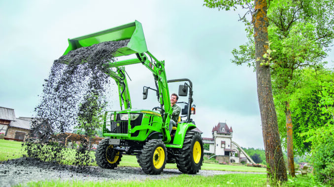
John Deere 3038e Repair Guide: Parts, Diagrams, Manuals

john deere

The John Deere 3038E is a compact utility tractor aimed at homeowners, acreage owners, and light property-management users who need more capability than a lawn tractor but do not necessarily need a larger farm tractor. Deere’s North American operator’s manual groups the 3038E with the 3032E, and common owner maintenance coverage for the 3038E centers on the diesel engine, fuel and air filtration, hydraulic/transmission system, front axle on MFWD machines, cooling system, and electrical controls.

For most owners in the USA and Canada, the 3038E is used for loader work, mowing with compatible attachments, driveway and property maintenance, material handling, and general small-acreage jobs. This guide covers practical repair decisions, symptom-based troubleshooting, maintenance priorities, common service parts, and a large FAQ so owners can separate realistic DIY work from jobs that are better handled by a Deere dealer.

John Deere 3038E model overview

The john deere 3038e sits in Deere’s compact utility tractor range rather than its residential mower lineup, which means owners deal with tractor-style systems such as diesel fuel filtration, hydraulic oil filters, cooling screens, front axle service on MFWD models, and safety interlocks rather than just mower-deck parts. Deere’s maintenance references for the 3038E also show longer-hour service intervals than a typical lawn tractor, including engine oil service at 200 hours or annually and several hydraulic/fuel filter services at 400 hours.

Typical systems owners need to understand on the john deere 3038e include:

  • Diesel engine and fuel system, including fuel filter and water-separator service.

  • Air intake and cooling system, including primary/secondary air filters and cooling screen cleaning.

  • Hydraulic and transmission system, including hydraulic and transmission/hydraulic filters.

  • Electrical and safety system, including seat switch, PTO switch, neutral start switch, battery, and light/electrical switches.

Several common service and repair parts owners regularly buy for the john deere 3038e include engine oil filter M806419, primary air filter M131802, secondary air filter M131803, hydraulic oil filter LVA14703, transmission/hydraulic filter LVA16054, battery TY26498, PTO switch LVA11437, neutral start switch RE12411, and fan belt M801821. Deere-focused parts retailers also list serial-number-sensitive filter kits, including LVA21128 for earlier serial ranges and LVA21037 for serial number 610001 and up.

John Deere 3038E troubleshooting approach

The best way to diagnose a john deere 3038e is to start with the symptom the owner sees rather than replacing parts by guesswork. Deere’s published maintenance and inspection guidance emphasizes routine checks such as engine oil, coolant, fuel sediment bowl, air restriction indicator, safety interlocks, transmission oil level, and cooling screens, which makes those the first places to look before moving to deeper diagnosis.

Main symptom groups on the john deere 3038e usually include:

  • Starting issues, such as no crank, slow crank, or crank-but-no-start.

  • Running issues, such as low power, rough running, smoke, or regeneration-related diesel concerns on later serial ranges with DPF-related parts listed.

  • Hydraulic and drive issues, such as weak loader response, noisy hydraulics, or poor movement.

  • Overheating and leak issues, especially from clogged cooling screens, coolant problems, hoses, or belt issues.

  • Electrical and safety-switch issues, including battery, seat switch, PTO switch, neutral start switch, or lighting/control faults.

John Deere 3038E emergency and immediate repair needs

Some john deere 3038e problems should be addressed right away because they affect safety or can lead to much more expensive damage. Fuel leaks, hydraulic leaks under pressure, overheating, charging failures, belt failures, and safety-interlock problems can all move from “inconvenient” to “machine-stopping” quickly if ignored.

John Deere 3038E starting issues

If the john deere 3038e will not crank, cranks slowly, or cranks but will not fire, stop and diagnose before repeated starting attempts drain the battery or overwork the starter. Hard starting can also indicate fuel delivery problems, interlock issues, or weak electrical supply rather than a single failed part.

Common causes:

  • Weak or failing battery TY26498.

  • Dirty or loose battery terminals.

  • Faulty neutral start switch RE12411.

  • PTO or seat safety-switch faults, including PTO switch LVA11437 or seat switch AM131968.

  • Fuel restriction from a dirty fuel filter or water-separator issue.

  • Air in the diesel fuel system after filter service.

Basic checks:

  1. Confirm PTO is off, range/gear selector is in the correct start position, and operator presence conditions are met.

  2. Check battery voltage, terminal tightness, and visible corrosion.

  3. Inspect the fuel sediment bowl/filter area for water or contamination.

  4. If recently serviced, bleed the fuel system as required before assuming a bad injector or pump.

John Deere 3038E vibration and noise

Unusual vibration or noise on the john deere 3038e should be treated seriously because it can point to loose wheel hardware, belt issues, driveline wear, hydraulic cavitation, or attachment-related problems. Deere’s maintenance charts specifically call for wheel bolt torque checks and regular lubrication, which are important because loose or dry components often show up first as noise and vibration.

Common causes:

  • Loose wheel bolts or hardware.

  • Worn or slipping fan/alternator belt M801821.

  • Dry grease points or hitch/linkage wear.

  • Attachment driveline or implement imbalance.

  • Hydraulic aeration or low fluid level.

Basic checks:

  1. Stop using the tractor and inspect wheel bolt torque and tire condition.

  2. Check visible belt condition and tension.

  3. Grease all scheduled fittings and inspect hitch/linkage wear points.

  4. Remove the implement from the equation if needed and test the tractor by itself.

John Deere 3038E overheating and leaks

A john deere 3038e that runs hot, smells hot, pushes coolant, or shows fluid under the machine needs immediate attention because heat and fluid loss can damage the engine, hydraulic system, or wiring. Deere’s routine service guidance specifically includes checking coolant level, cleaning cooling air screens daily, checking radiator hose clamps, and cleaning radiator fins at longer intervals.

Common causes:

  • Plugged cooling air screens or dirty radiator fins.

  • Low coolant level.

  • Loose or aging radiator hoses, including upper LVU17635 or lower LVU17636.

  • Faulty thermostat M811034 or leaking thermostat gaskets M805834/M805835.

  • Slipping or broken fan belt M801821.

Basic checks:

  1. Shut the tractor down and let it cool before opening anything pressurized.

  2. Clean screens and inspect radiator fins for packed debris.

  3. Check coolant level and hose condition.

  4. Inspect the fan belt and verify it is intact and properly tensioned.

John Deere 3038E transmission and hydraulic problems

If the john deere 3038e moves poorly, the loader is weak, or hydraulics sound noisy, do not keep working it hard because low oil level, restricted filters, or internal wear can get worse quickly. Deere service references for the 3038E identify both a hydraulic oil filter and a transmission/hydraulic filter, with an initial transmission/hydraulic filter change after 50 hours and later service at 400-hour intervals.

Common causes:

  • Low transmission/hydraulic oil level.

  • Restricted hydraulic or transmission/hydraulic filter, including LVA14703 or LVA16054.

  • Air entering the hydraulic system.

  • Dirty fluid or overdue service.

  • Internal pump, valve, or hydro/mechanical drivetrain issues requiring dealer diagnosis.

Basic checks:

  1. Verify oil level with the tractor on level ground using the correct procedure from the operator’s manual.

  2. Review service history to see whether the 50-hour or 400-hour filter change has been missed.

  3. Look for leaks around hoses, couplers, filter bases, and axle/hydraulic areas.

  4. If symptoms remain after level and filter checks, move toward dealer testing rather than guessing at hydraulic internals.

John Deere 3038E electrical problems

Electrical problems on the john deere 3038e often show up as no-start, intermittent shutoff, dead lights, or erratic switch behavior. Because Deere parts listings for this model include multiple switches and bulbs, owners should first separate a power-supply issue from a single failed switch or lamp circuit.

Common causes:

  • Weak battery TY26498.

  • Blown fuse or poor fuse connection.

  • Failed headlight switch AM124875, PTO switch LVA11437, turn signal switch LVA12928, or seat switch AM131968.

  • Corroded grounds or battery cables.

  • Faulty oil pressure or temperature-related sender/switch faults.

Basic checks:

  1. Test the battery and charging system first.

  2. Check fuses before replacing switches.

  3. Inspect harness plugs around the battery, dash, and operator platform.

  4. Replace individual switches only after confirming they are actually the fault.

Summary:

Most reported issues

Area Typical symptom Likely causes / first checks
Hydraulic loader and 3-point hitch Loader slows, feels weak or jerky, hitch responds poorly, loader/bucket drifts down while parked Check hydraulic/transmission oil level and correct fluid specification; look for hose/fitting leaks, damaged cylinders, air ingestion, and restricted filters. Cylinder internal leakage is a plausible cause of persistent loader or backhoe drift.
Hydrostatic transmission Weak travel drive, inconsistent forward/reverse response, overheating, or poor pulling ability Verify oil level/condition, filters, correct engine speed, linkage adjustment, and whether a brake is dragging. Reports also mention HST pressure/output complaints, though these require proper pressure diagnosis rather than guessing at a pump failure.
Engine overheating Temperature climbs during mowing, brush cutting, or dusty work A plugged radiator/screen is a frequent practical cause. Clean debris from the grille, radiator and cooling area; then check coolant level, belt condition, and fan operation. One owner specifically reported overheating while mowing that improved after cleaning.
Starting and stalling Slow/no start, intermittent shutdown, rough running, loss of power Start with battery terminals, battery condition, fuses, fuel quality, fuel filter, fuel-line restrictions, and air-filter blockage. Safety-interlock faults can also imitate an engine problem.
Seat/brake safety switches Engine shuts off unexpectedly, no-start condition, PTO or travel-related interlock trouble Seat and brake sensors/switches appear in owner reports. Inspect connectors, switch adjustment, damaged wiring and correct pedal/seat operation before replacing components. Do not bypass safety circuits.
Front axle / front hub seals Oil seepage around front hubs or axle ends Front axle seal leakage is repeatedly mentioned by owners. Monitor axle-oil level and repair promptly if the leak is active; running low risks expensive internal damage.
Steering Excess steering free play, weak power steering, hard steering Check hydraulic oil level first, then front-tyre condition/pressure, steering linkage, column/coupler wear, and hydraulic leaks.
PTO problems PTO will not engage, drops out, or operates intermittently Check PTO switch, relevant fuses/connectors, seat/interlock operation and PTO-clutch wiring.
Limited lift/pulling performance Loader struggles with wet soil/gravel; engine bogs in heavy mowing Some dissatisfaction is capacity-related rather than a defect. The 3038E is a lightweight economy compact tractor, so wet material, a loaded bucket, steep ground, and an oversized mower/shredder can exceed practical capability.

Issues worth inspecting before purchase

For a used 3038E, I would make these checks non-negotiable:

  1. Cold start it and confirm it starts cleanly, idles evenly, and has no warning indicators.

  2. Run it to full operating temperature, then test it under load—ideally with the mower, loader, or another implement attached.

  3. Cycle the loader and three-point hitch repeatedly. Look for jerky action, hesitation, hydraulic whining, leaks, or a bucket that lowers rapidly after being raised.

  4. Park the loader raised safely and observe for drift. Some very gradual settlement can occur, but a quick or severe drop deserves diagnosis.

  5. Drive in all HST ranges, forward and reverse, on level ground and under moderate load. It should respond progressively and not surge, fade, or feel unusually weak.

  6. Inspect both front hubs and axle seals for wet oil, dirt stuck to oil residue, and low front-axle fluid.

  7. Check the cooling pack for packed grass, chaff and dust—especially if it has been used for mowing.

  8. Test every interlock and electrical function: seat switch, brake-related starting operation, PTO engagement, lights, gauges and tachometer.

  9. Look beneath the floorboard for vulnerable hydraulic-line damage, especially if the tractor has worked in woodland, brush, or rough ground.

Practical prevention

The best way to avoid many of the reported complaints is relatively routine:

  • Blow out the radiator/screen regularly during dry mowing or brush work.

  • Keep the hydraulic/transmission oil at the specified level and use the specified fluid and filters.

  • Replace fuel filters and inspect the air filter on schedule.

  • Avoid treating a compact loader as a larger utility tractor loader—especially with wet dirt, dense gravel, or a load held high.

  • Repair front-axle and hydraulic leaks early rather than simply topping fluids up.

  • Keep the underside and hydraulic plumbing clear of branches and stumps.

  • Diagnose intermittent shutdowns through the safety-switch and wiring system before assuming an injection or engine fault.

Bottom line

The most credible 3038E pattern is not one single catastrophic design failure. It is a set of conventional compact-tractor weak points: hydraulic leakage/drift or weak response, cooling blockage during dusty work, front axle seal leakage, electrical/interlock faults, and some HST-performance complaints. A well-serviced example that passes a hot, loaded hydraulic-and-drive test can still be a useful machine; one with weak hydraulics, active front-hub leaks, or unexplained HST weakness should be priced as a repair project.

How to troubleshoot 3038E hydraulic slow downs

Troubleshoot a slow 3038E hydraulic system by first separating a whole-system problem from a loader-only or 3-point-only problem. Begin with oil level/condition, filter condition, engine rpm, warm-up, obvious leaks, and the 3-point rate-of-drop valve; those are the causes Deere’s troubleshooting guidance identifies before pump or valve work.

Safety first

  • Park on level ground, lower implements and loader to the ground, set the parking brake, and shut the engine off before inspecting hoses, filters, or linkages.

  • Never search for a pressurized hydraulic leak with your hands. Hydraulic injection injuries can be serious.

  • Relieve hydraulic pressure by moving the loader/SCV controls through all positions with the engine off before coupling or uncoupling hydraulic hoses.

  • Do not work beneath a raised loader or suspended implement unless it is mechanically supported.

Identify the pattern

Use this quick isolation test before buying parts.

What is slow? Most likely area First checks
Loader, 3-point hitch, steering, and hydraulic remotes are all slow Shared oil supply, restricted filter, air leak/cavitation, low engine speed, or pump/relief issue Fluid level, correct oil, filter, leaks, engine rpm, cold-weather behaviour
Loader and remotes are normal, but 3-point is slow 3-point control, rate-of-drop valve, linkage, internal hitch valve/cylinder, or excessive implement weight Rate-of-drop setting, hitch linkage, load, lift response at rated rpm
Loader is slow but 3-point works normally Loader quick couplers, SCV/joystick linkage, loader hose restriction, cylinder or valve problem Fully seated couplers, kinked hoses, loader valve/SCV function
Slow only while cold, then improves Normal cold-oil restriction or unsuitable/contaminated oil Warm it briefly, then reassess; check oil type and water contamination
Slow once hot, with hydraulic whine or worsening performance Restriction, low oil, air entering suction side, overheated oil, or pump wear Filter, oil level, leaks, cooling/operating load; arrange pressure testing if unresolved

The operator’s manual notes that hydraulic operation can be slow in cold weather because cold oil does not pass as easily through the system; it also cautions against excessive warm-up, specifying no more than about 2–3 minutes to avoid pump or relief-valve damage.

Step-by-step checks

1. Run the engine at working speed

Hydraulic flow depends on engine speed. Test with the engine at a sensible working rpm—not at idle—and compare it with the response at idle.

If the loader or hitch becomes acceptably quick once rpm rises, that is usually normal flow behaviour rather than proof of a hydraulic failure. Deere’s troubleshooting table specifically lists low engine speed as a cause of slow 3-point lift operation.

2. Check hydraulic/transmission oil level

With the tractor safely parked according to the operator’s manual procedure:

  • Check the transmission/hydraulic oil level.

  • Look at the oil’s appearance where possible.

  • Do not accept milky or cloudy oil as normal; it can indicate water contamination.

  • Check for fresh leaks at filter seals, hose fittings, loader couplers, valve blocks, axle areas, and underneath the tractor.

Deere lists low oil, oil leaks, and water-contaminated oil among causes of sluggish hydraulic operation.

If the level is low, do not simply top it up and continue working. Find the source of the loss.

3. Confirm the correct oil was used

Incorrect hydraulic/transmission oil can noticeably affect response, especially in colder conditions. Deere’s manual specifically lists improper oil type as a cause of slow hydraulic operation and directs owners to drain and refill with the correct specified fluid where necessary.

This matters particularly on a used tractor with uncertain service history. Check service invoices or ask the previous owner/dealer exactly what fluid was installed rather than relying on colour or generic claims that an oil is “universal.”

4. Inspect and service the hydraulic filter

A restricted hydraulic oil filter is one of Deere’s direct listed causes of slow operation and weak 3-point performance.

  • Check the service-hour record.

  • If the filter interval is unknown, treat it as due.

  • Replace the filter using the correct part and verify that the replacement is properly installed.

  • If removed oil or filter media suggests metal, severe contamination, or water, stop treating it as routine maintenance and investigate the source before operating heavily.

5. Test all hydraulic functions

At operating rpm, with the tractor warmed normally, test:

  1. Raise and lower the loader with an empty bucket.

  2. Curl and dump the bucket.

  3. Raise and lower the three-point hitch.

  4. Operate rear remotes, if fitted.

  5. Turn the steering wheel at a standstill and while moving slowly.

Interpret the results:

  • Everything slow: concentrate on oil, filter, pump supply, suction-side air leak, relief/pressure, or a common hydraulic issue.

  • Only one circuit slow: focus on that circuit’s control valve, couplers, hoses, cylinders, linkage, or load.

  • Function improves after cycling: this can point to cold oil, marginal flow, or aeration; it should not be ignored if it recurs once warm.

3-point hitch checks

If your primary complaint is slow lift or poor lowering on the rear hitch, do these before assuming the pump has failed.

Rate-of-drop control

The 3-point hitch has a rate-of-drop adjustment. A setting that is too closed will make the hitch descend slowly—or appear not to descend at all. Deere specifies:

  • Turn the rate-of-drop knob counter-clockwise to increase drop speed.

  • Turn it clockwise to decrease drop speed.

This adjustment changes lowering speed, not lift power. If the hitch is slow going up, check engine rpm, oil level, filter, fluid condition, excessive implement weight, and linkage/valve issues.

Excessive load

Test the hitch with no implement attached, then repeat with the implement installed. Deere lists an excessive hitch load as a cause of poor hydraulic performance and slow lift.

If it raises empty arms promptly but labours or stalls with the implement, confirm the implement’s actual weight and centre of gravity. A ballast box, mower, implement extension, or attachment mounted far rearward can make a load effectively harder to lift.

Linkage and lever movement

Watch the external linkage while moving the 3-point control lever. A disconnected pin, seized linkage, or lost retaining clip can produce erratic or partial response. Owner reports also describe control-linkage faults causing abnormal 3-point behaviour.

Loader-specific checks

If the three-point works normally but the loader is slow:

  • Inspect each quick coupler. A coupler that looks connected can still be incompletely seated and restrict flow.

  • Check for kinked, crushed, rubbing, or internally damaged hoses.

  • Ensure the joystick/SCV returns correctly to neutral and has full movement in raise/lower and curl/dump directions.

  • Compare both loader functions. If lift is slow but bucket curl is normal, suspect the lift circuit, cylinder, hose, or valve spool rather than the entire hydraulic system.

  • Look for external cylinder leakage and for unexplained cylinder drift with the control in neutral.

Do not loosen fittings to “test pressure.” Proper diagnosis of suspected pump, relief-valve, or SCV faults requires the correct hydraulic gauge, fittings, and Deere pressure specifications.

When to stop and use a dealer

Arrange a hydraulic pressure and flow test if any of these apply:

  • The oil level is correct, oil is clean/correct, the filter is current, and the system remains slow at working rpm.

  • The tractor is slow both cold and fully warm.

  • Several hydraulic functions are weak at once.

  • You hear persistent pump whine, growling, or cavitation.

  • The hydraulic oil repeatedly foams, suggesting air ingestion.

  • The 3-point will lift empty but not a normal-rated implement.

  • You find metal debris, heavy water contamination, or a recurring leak.

  • The loader/hitch response is intermittent or accompanied by hydrostatic-drive weakness.

Deere lists a worn hydraulic pump as a potential cause after the basic oil/filter/load checks; that is not a sensible DIY assumption without pressure/flow testing.

How to check hydraulic filter and fluid condition

On a 3038E, the hydraulic oil is shared with the transmission, so the checks are usually listed as “transmission oil” and “hydraulic suction oil filter.” Check the oil level and condition first; then inspect the filter’s service history and replace it if it is due or unknown. Deere’s 3038E manual includes specific procedures for checking transmission oil and changing the transmission oil and hydraulic suction filter.

Before you start

  1. Park on firm, level ground.

  2. Lower the loader, three-point hitch, and any implement fully to the ground.

  3. Set the parking brake, place the range/transmission controls in the prescribed parked/neutral condition, shut off the engine, and remove the key.

  4. Allow the machine to cool if it has been working—oil, housings, and filters may be hot.

  5. Wipe dirt away from the dipstick/filler area and filter area before opening anything.

Do not crawl beneath a loader or implement supported only by hydraulics. Never use fingers or hands to look for a pressurised hydraulic leak; high-pressure fluid can penetrate skin.

Check fluid level

On the 3038E, use the transmission/hydraulic oil dipstick or level-check point specified for your exact model year. The exact position can vary slightly between earlier and later production versions, so use the operator’s manual matching the tractor serial number where possible.

Basic process

  1. With the tractor level and attachments fully lowered, locate the transmission/hydraulic dipstick or level-check plug.

  2. Clean the surrounding area thoroughly.

  3. Remove the dipstick, wipe it with a lint-free rag, reinstall it fully, then remove it again.

  4. Read the oil level against the marked operating range.

  5. If low, add only the specified transmission/hydraulic oil through the correct filler point, adding small amounts and rechecking rather than overfilling.

  6. Refit the dipstick and clean any spillage.

A low level can make the pump draw air, causing slow or jerky loader/hitch operation, pump whine, foaming, and inconsistent response. However, an unexplained low level also means you should inspect for a leak rather than repeatedly topping it up.

Assess fluid condition

Put a small amount of oil from the dipstick onto a clean white lint-free rag or into a clear container. You are looking for four things.

What you see What it can indicate Recommended response
Clear/clean-looking oil with no strong burnt smell Usually normal appearance Continue diagnosing flow, controls, couplers, or circuit-specific issues if hydraulics remain slow
Milky, cloudy, or creamy oil Water contamination Avoid heavy operation; identify water entry and arrange an oil/filter change
Very dark oil or burnt/overheated smell Oxidised/overheated fluid or neglected service Change oil and filter; investigate overheating, excessive load, cooling, or chronic restriction
Grit, shiny flakes, or metallic debris Possible internal wear or component damage Do not treat as a routine service; retain a sample and have the system assessed
Visible foam or persistent bubbles Air entering the system, low oil, or aeration Check oil level, suction-side connections, seals and filter installation

A small amount of colour variation alone is not conclusive. The more meaningful warning signs are milkiness, burnt odour, foam, grit, and metal.

Check the filter

The 3038E has a hydraulic suction filter associated with its transmission/hydraulic system. Deere’s service information specifically calls this procedure “Changing Transmission Oil and Hydraulic Suction Oil Filter.”

External inspection

With the tractor off and cooled:

  • Locate the hydraulic/transmission filter beneath or alongside the transmission area, using the manual for your serial-number version.

  • Look for wetness around the filter gasket, filter body, hose connections, and nearby fittings.

  • Check whether the filter is dented, punctured, crushed, or heavily contaminated externally.

  • Confirm the filter is not loose and that there is no obvious evidence of an incorrect or poorly fitted replacement.

  • Check the machine’s hour meter and service records.

A filter cannot generally be judged as clear internally while it is installed. If service timing is unknown, a replacement with the correct specification filter is more reliable than assuming it is fine from its outside appearance.

When filter replacement is sensible

Replace the hydraulic suction filter if:

  • Its scheduled interval has been reached.

  • The tractor’s service history is unknown.

  • Hydraulic operation is slow across several functions.

  • The oil is visibly contaminated or milky.

  • A recent repair opened the hydraulic system.

  • The filter seal or body leaks.

  • You find metallic debris or abnormal material in drained oil.

Use the correct Deere-approved or equivalent filter for the precise 3038E variant and production year. An incorrect filter, damaged seal, or air leak at the filter can contribute to restricted flow or aeration.

After topping up or servicing

  1. Reinstall everything securely and clean residual oil from the tractor.

  2. Start the engine at low idle.

  3. Check around the filter and fill/check points for leaks.

  4. Slowly cycle the loader and three-point hitch several times, without holding controls against their stops.

  5. Recheck the oil level after the system has stabilised.

  6. Test hydraulic speed again at normal working rpm.

If the loader, steering, three-point hitch, and remotes all remain slow after the level is correct and the filter/oil service is current, the next diagnostic step is professional hydraulic pressure and flow testing. That separates a restriction, relief-valve issue, suction-side air leak, or pump-output problem without blindly replacing expensive parts.

On a John Deere 3038E, overheating is most often caused by restricted airflow through the cooling package—grass, chaff, dust, seeds, or mud blocking the grille screen, radiator, or cooling fins—particularly during mowing, shredding, brush work, and dry loader work. Low coolant, coolant leaks, a slipping fan belt, thermostat or water-pump faults, and less commonly an electrical-ground/coolant-electrolysis issue can also be involved.

Most likely causes

Cause Typical clues What to check
Plugged grille, radiator screen, or fins Temperature rises while mowing/shredding; worsens in dry grass or dusty conditions; improves after stopping Remove and clean screens; inspect radiator and cooling-pack fins with engine cool
Debris between coolers Front screen looks clean but it still overheats Inspect the full cooling stack—not just the visible outer face—for packed chaff between radiator/oil-cooler sections
Low coolant Gradual temperature rise; heater output weak if fitted; visible seepage or recurring need to top up Check coolant only when cold; inspect hoses, clamps, radiator cap area, water pump, and ground beneath tractor
Failing or loose fan belt Belt squeal; poor fan speed; possible charging irregularities Inspect for looseness, cracking, glazing, oil contamination, or missing belt ribs
Thermostat sticking / water-pump circulation fault Overheats despite a clean radiator and correct coolant level; upper/lower hose temperatures may be abnormal Dealer or competent technician should verify thermostat opening and coolant circulation
Old, contaminated, or incorrect coolant Rusty, murky, oily, or contaminated coolant; recurring cooling-system problems Flush and refill to Deere specification after diagnosing the source
Overloading the engine Happens only with a heavy mower, tall wet grass, sustained high PTO load, steep ground, or excessive loader work Reduce load/ground speed; use appropriate PTO rpm and avoid lugging engine
Electrical grounding/electrolysis issue Persistent problem not explained by airflow or coolant level; possible cooling-system corrosion Earlier owner reports reference a Deere technical-service issue involving poor grounding and electrolysis; needs correct voltage testing and coolant/ground repair rather than guesswork.

First checks to do

1. Stop before it enters the red

If the temperature gauge climbs abnormally, stop PTO work, reduce engine load, and let the engine cool. Do not remove the radiator cap while hot: pressurised coolant can cause severe burns.

A little temperature movement under heavy work can be normal; a steadily rising needle, warning light, steam, coolant smell, or coolant loss is not.

2. Clean the complete cooling pack

With the engine fully cool:

  • Open or remove the front/side screens as designed.

  • Remove grass, chaff, dirt, and insect debris from the grille and radiator face.

  • Use low-pressure air blown from the engine side outward where practical, so debris exits the way it entered.

  • Use water gently only if appropriate, then allow the area to dry; avoid bending delicate fins.

  • Check behind the visible radiator surface. Packed debris can lodge between cooling components even when the front looks reasonably clean.

  • Clean around the engine compartment too, particularly after brush cutting.

On compact tractors such as the 3038E, cooling-pack blockage is common because mowing and brush work throw fine chaff directly into the air intake. Cleaning the screens and fins is the logical first repair step before replacing cooling-system parts.

Check coolant and leaks

Only when the engine is cold:

  1. Check the coolant reservoir and, where the manual procedure permits, the radiator level.

  2. Look for wetness, crusty dried coolant residue, or staining around:

    • Upper and lower radiator hoses

    • Hose clamps

    • Radiator seams and cap area

    • Water-pump area

    • Thermostat housing

  3. Inspect the ground after parking for drips.

  4. Examine coolant condition. Clean coolant should not look oily, heavily rusty, muddy, or milky.

A low coolant level does not identify the fault by itself. Repeated loss means there is an external leak, an internal cooling-system problem, or a cap/overflow issue that needs finding.

Check belt and workload

Inspect the fan/alternator belt with the engine off:

  • Replace it if cracked, frayed, shiny/glazed, oil-soaked, or obviously loose.

  • A slipping belt can reduce fan speed and coolant circulation while also affecting charging.

  • Investigate a squeal promptly, particularly if it occurs under load or as temperature climbs.

Also match the tractor to the job:

  • Keep engine rpm high enough to maintain cooling airflow and PTO speed.

  • Slow ground speed in dense or tall material rather than lugging the engine.

  • Take narrower passes in heavy grass/brush.

  • Reduce loader load or stop periodically in unusually hot/dusty work.

When basic checks are not enough

If the radiator and screens are clean, coolant level is correct, the belt is sound, and the 3038E still overheats, avoid continued use until it is diagnosed. A workshop should pressure-test the cooling system and cap, confirm thermostat operation, verify water-pump circulation, and inspect for internal restrictions or combustion-gas intrusion.

For some earlier 3038E reports, owners have described a Deere technical-service issue involving an inadequate ground path and electrolysis in the cooling system. That is not a first assumption, but it becomes relevant when ordinary airflow, coolant, leak, belt, thermostat, and circulation checks do not explain the overheating. It requires a correct meter test and, if confirmed, proper grounding and coolant corrective work.

To test a John Deere 3038E for coolant electrolysis, use a digital multimeter to measure DC voltage between the coolant and a known-good chassis/engine ground. The probe must touch only the coolant—not the radiator neck, tank, or any metal—because metal contact invalidates the reading. A result under roughly 0.10 V (100 mV) is reassuring; readings approaching or above 0.30 V (300 mV) warrant investigation for stray current, poor grounds, charging-system faults, or degraded coolant.streetmusclemag+2

What you need

  • A digital multimeter with DC-voltage measurement and preferably millivolt resolution.

  • Clean access to coolant in the radiator filler neck or a pressurised expansion/degas tank.

  • A clean bare-metal engine/block ground or direct access to the negative battery post.

  • Safety gloves and eye protection.

Avoid testing through an unpressurised coolant recovery bottle if it may not contain active circulating coolant. Test at the radiator filler neck or pressurised coolant reservoir where possible.

Safety setup

  1. Start only with the engine fully cold if you must remove a radiator or pressurised reservoir cap.

  2. Park on level ground, set the parking brake, lower implements, and keep hands clear of belts, fan, and rotating components.

  3. Never remove a radiator cap from a hot or pressurised cooling system.

  4. Do not allow either meter lead to contact the fan, belts, battery positive terminal, or moving parts.

  5. Do not use the multimeter’s resistance/ohms setting on a live electrical system. Use DC volts first; later, take an AC-voltage reading as a secondary check.awrracing+1

DC-voltage test

1. Set the meter

  • Select DC volts—shown as V⎓, VDC, or a solid line over a dashed line.

  • Use auto-ranging, or select the 2 V / 20 V range.

  • If the meter has a millivolt setting, you may use it once you know the reading is below 1 V.

2. Connect the probes

  • Connect the black/negative probe to the clean negative battery post. A clean, unpainted engine block point is an acceptable cross-check.

  • Suspend the red/positive probe in the coolant.

  • Keep the metal tip immersed but ensure it touches coolant only. It must not touch the filler neck, radiator core, cap seat, reservoir wall, hose clip, or any other metal.

This measures the electrical potential between the coolant and the tractor’s ground circuit.streetmusclemag+2

3. Record readings in stages

Take readings and write them down:

Test condition What it helps reveal
Engine off, key off Baseline chemical/galvanic activity in the coolant
Key on, engine off Electrical circuits energised without alternator charging
Engine idling Stray current or charging/ground-related voltage
Approximately 1,500–2,000 rpm Charging-system or ground faults that appear with alternator output
PTO/working electrical loads activated where safe A voltage spike tied to a particular circuit or accessory

For the 3038E, useful load changes include switching lights on, engaging electrically controlled accessories where applicable, or switching the PTO only if it is safe and the implement is disconnected or otherwise properly controlled. The principle is to change one electrical load at a time and watch whether the reading rises sharply.autoserviceworld+2

Reading the result

Different cooling-system sources set different action thresholds, so treat the number as a diagnostic guide—not a standalone verdict.

DC reading Practical interpretation
0.00–0.05 V Very low activity; generally reassuring
About 0.05–0.10 V Usually acceptable, but record it and compare hot versus cold readings
Over 0.10 V Worth investigating, especially if the coolant is old or there is unexplained radiator/heater-core corrosion
0.30 V or more Abnormal enough to treat as a real electrolysis/stray-current issue until proven otherwise
Over 0.40 V, or a sharp rise with rpm/load Strong clue of a charging, grounding, wiring, or accessory-circuit problem

Several technical references use 0.30 V as the maximum acceptable reading, while some radiator specialists use 0.10 V as the level at which corrective action should begin. The key warning signs are a reading that is high, rises substantially as rpm increases, or spikes when a particular circuit is turned on.streetmusclemag+3

Test AC voltage too

After the DC test, repeat using AC volts (V~) on the lowest suitable range.

  • Keep the black probe on battery negative or clean engine ground.

  • Keep the red probe immersed in coolant only.

  • Repeat at idle and at roughly 1,500–2,000 rpm.

Unexpected AC voltage can point to alternator diode/ripple problems. The formal cooling-system guidance recommends checking both AC and DC voltage rather than DC alone.awrracing+1

If the reading is high

First determine whether it is mainly coolant chemistry or an active electrical fault:

  1. Repeat the reading with engine off and all electrical systems off.

  2. Repeat with the engine at idle, then at higher rpm.

  3. Switch electrical loads on and off one at a time.

  4. If the reading rises with engine speed or one circuit, inspect battery terminals, engine-to-frame ground straps, chassis grounds, alternator wiring/output, accessory wiring, and any added electrical equipment.

  5. If the reading remains high even with the battery disconnected, the coolant itself may be conductive because it is old, contaminated, mixed incorrectly, or chemically depleted. Replace coolant only after fixing any electrical cause; otherwise the new coolant can be damaged quickly.techtips+1

On a 3038E with unexplained overheating or recurring radiator/cooling-system corrosion, have a Deere-capable technician check ground integrity and charging-system ripple as part of the diagnosis. Do not assume electrolysis is the cause until you have first ruled out the more common problems—blocked radiator fins/screens, low coolant, a coolant leak, a poor belt, thermostat restriction, or inadequate coolant circulation.

How do I trace a stray current in a John Deere 3038E

Trace a suspected stray current on a 3038E by keeping a voltmeter connected between the coolant and battery negative, then changing one electrical condition at a time until the voltage drops or spikes. Start with grounds and alternator ripple, because a poor engine-to-battery/chassis return path or charging fault can force current to seek another path through the cooling system. Deere’s technical documentation for 3038E-family tractors includes dedicated electrical repair, battery/starter/alternator, and ground-point sections—use the electrical diagram for your exact serial-number range when you move beyond basic checks.

Safety and setup

This procedure is for diagnosing electrical leakage associated with coolant electrolysis—not for working on a hot or pressurised cooling system.

  • Begin with the engine cold before removing any radiator or pressurised coolant-reservoir cap.

  • Park level, lower the loader and implements, set the parking brake, and keep clear of PTO shafts, belts, fan, and moving linkage.

  • Use a digital multimeter on DC volts, preferably with a millivolt range.

  • Put the black lead directly on the negative battery post. Do not begin on painted sheet metal.

  • Suspend the red probe in the coolant without allowing it to touch the radiator neck, core, filler tube, cap seat, reservoir hardware, or engine metal.

  • Keep the probe at the same depth/position for every comparison reading.

You are looking for a repeatable change in voltage as circuits are switched on and off. Some industry guidance treats more than 50 mV as worth investigating, while readings around 0.30 V and above are widely treated as clear evidence of an abnormal stray-current path.

Establish a baseline

Record the reading—not just a pass/fail result—at each stage.

Condition What it tells you
Battery connected, key off, engine off Base coolant chemistry/galvanic voltage
Key on, engine off Voltage caused by powered tractor circuits before alternator charging
Engine idling Ground-path and charging-system contribution
About 1,500–2,000 rpm Alternator output, regulator, diode/ripple or high-resistance ground faults that worsen with rpm
Electrical loads switched on one at a time Identifies the circuit that changes the coolant-to-ground voltage

A meaningful fault clue is a reading that rises sharply from key-off to key-on, from idle to higher rpm, or when a specific circuit is energised.

Isolate the offending circuit

1. Key-off baseline

With the engine off and key removed:

  • Take and record the DC-voltage reading.

  • If it is already high, suspect depleted/contaminated coolant, a continuous live aftermarket circuit, or a battery/ground problem.

  • Disconnect aftermarket accessories first where fitted: beacon, work lights, USB charger, sprayer wiring, trailer-brake controller, stereo/radio, winch, camera, or added implement harnesses.

2. Key-on comparison

Turn the key to ON without starting:

  • Watch the meter for a change.

  • If voltage rises, the source is in a key-switched circuit, such as instrument-panel circuits, safety/interlock wiring, relays, solenoids, lighting feeds, or an attached implement circuit.

  • Turn the key off, then unplug or isolate one likely accessory/circuit at a time and repeat.

Do not pull random connectors with the key on. Switch off first, disconnect, then re-test.

3. Engine-running and rpm test

Start the tractor and observe the voltage at idle. Then increase speed gradually to approximately 1,500–2,000 rpm.

  • Voltage rises with rpm: prioritise alternator, regulator, alternator ground, charging cable, battery negative cable, and engine-to-frame ground strap.

  • Voltage is stable at rpm but rises when a load is selected: follow the individual load circuit.

  • Voltage remains high in every condition: investigate coolant condition and all major ground paths, then use the wiring diagram for systematic circuit isolation.

A technical manual for the 3038E family includes diagnostic material for the battery, starter, alternator and ground points—the appropriate source for exact connector, fuse, and grounding-location identification.

4. Switch loads one by one

At idle, turn one item on, then off, waiting for the meter reading to settle each time. Record the voltage after each change.

Useful tests on a 3038E include:

  • Headlights and hazard/flashers.

  • Work lights or beacon, especially if added later.

  • PTO circuit, only if the area is safe and the implement is disconnected or safely managed.

  • Any rear implement electrical connector.

  • 12-volt socket, USB adaptor, sprayer, spreader, trailer, or other attachment wiring.

  • Operator-presence, PTO, brake, and neutral circuits only through normal controls—do not bypass safety switches.

The circuit that causes a repeatable increase is your leading suspect. A fault in a lamp, fan, accessory, harness, or poor earth can make electrical current seek an alternate path through coolant and radiator components.

Check grounds properly

Disconnect the negative battery cable first before removing, cleaning, or tightening ground connections.

Inspect and service, at minimum:

  • Battery negative cable at the battery terminal.

  • Battery negative cable connection to engine block.

  • Engine-to-frame/chassis ground strap.

  • Alternator case/grounding path and alternator output connections.

  • Grounds near the dash, lights, rear harness, and any added accessories.

  • Ground points affected by paint, rust, oil, corrosion, loose bolts, damaged eyelets, or frayed cable strands.

Clean mating surfaces to bare sound metal, tighten securely, and protect the completed external connection against corrosion. Do not add a random ground wire to the radiator as a substitute for finding the bad return path; correct the failing ground/circuit first.

After each repair, repeat the same coolant-voltage test conditions. The repaired connection should produce a lower and more stable reading.

Verify voltage drop

A simple continuity check can miss a bad ground because it uses tiny current. Use a voltage-drop test under load instead.

  1. Reconnect the battery.

  2. Set the meter to DC volts.

  3. Put one probe on the negative battery post and the other on clean engine block metal.

  4. Crank the engine briefly or turn on significant electrical loads.

  5. Record the voltage.

Then repeat between:

  • Battery negative post and chassis/frame.

  • Engine block and chassis/frame.

  • Alternator case and engine block.

  • Ground-side terminal of a suspect accessory and battery negative.

A significant voltage drop that appears under load identifies excessive resistance in that cable, ground point, fastener, or connection. Test each section separately to narrow it down. Deere’s repair documentation specifically treats ground points and the starter/alternator system as diagnostic sections rather than relying on visual checks alone.

Check alternator AC ripple

A damaged alternator diode can introduce excessive AC ripple, which may show up as coolant voltage or electrical instability.

  1. Leave the coolant-probe arrangement in place.

  2. Change the meter to AC volts on the lowest appropriate range.

  3. Measure at idle and again near 1,500–2,000 rpm.

  4. Repeat with lights/work lights on.

If AC voltage increases significantly with engine speed, or electrical charging behaviour is erratic, have the alternator and regulator bench-tested or tested on the tractor. Do not replace it based only on the coolant test; confirm with a charging-system test.

Finish the diagnosis

Once the electrical source is corrected:

  • Replace coolant if it is old, milky, rusty, mixed incorrectly, or suspected of contamination.

  • Use the coolant type and water quality specified by Deere.

  • Inspect radiator, heater/cooling passages, water pump and fittings for corrosion damage.

  • Recheck coolant-to-battery-negative voltage at key-off, key-on, idle, and working rpm.

  • Continue checking the actual overheating cause as well: radiator screen/fins, coolant level, belt, thermostat, water pump and engine loading remain more common explanations for a hot-running 3038E than electrolysis.

How do I check voltage drop on the battery cable

Check battery-cable voltage drop while the starter is cranking, because a corroded terminal or damaged cable may look fine and show continuity at rest but fail when it must carry high current. On a 3038E, test the positive cable and negative/ground cable separately with the multimeter on DC volts. A healthy heavy starter circuit normally loses no more than about 0.5 V total, with roughly 0.3 V or less on the positive side and 0.2 V or less on the ground side during cranking.

What you need

  • Digital multimeter with DC-voltage setting.

  • Meter leads/clips long enough to reach battery and starter.

  • An assistant to turn the key to START, or a method to safely view the meter while cranking.

  • Eye protection and a clear, safe work area.

Use the battery posts, not the cable clamps, as your measurement points. Testing from a post to a clamp is also useful later to find a bad terminal connection.

Safety and preparation

  1. Park on level ground; lower loader and implements.

  2. Set the parking brake, place controls in the normal start-safe positions, and keep the tractor in neutral.

  3. Keep hands, clothing, tools, and meter leads away from belts, fan, exhaust, and moving parts.

  4. Ensure the battery is reasonably charged before diagnosis. A resting battery around 12.4 V or above is a useful baseline; charge it first if it is substantially lower.

  5. Set the meter to DC volts (V⎓ / VDC). Use the 2 V range if available; otherwise use 20 V DC.

  6. Crank in short bursts—about 4–5 seconds maximum per test—then let the starter cool briefly.

A voltage-drop test does not require disconnecting cables. You are measuring voltage across the cable and its connections under load.

Positive cable test

This checks the complete high-current supply route: battery positive post, positive clamp, cable, connections, solenoid contact and starter power terminal.

  1. Put the red probe directly on the battery positive post—the actual lead post, not the clamp.

  2. Put the black probe on the starter motor’s large battery-feed terminal/stud.

  3. Have an assistant crank the engine.

  4. Read the highest voltage displayed only while cranking.

Interpret it

Positive-side drop while cranking Meaning
0.00–0.20 V Excellent
0.20–0.30 V Generally acceptable for a tractor starter cable
0.30–0.50 V Borderline; inspect and clean all positive-side connections
Over 0.50 V Excessive resistance in the cable, terminal, solenoid connection, fusible link, or starter feed

A commonly cited overall starter-circuit guideline is about 0.2–0.5 V, with around 0.3 V on the positive side.

Negative cable / ground test

This checks the return path: starter case to engine block, engine-to-frame ground strap, battery negative cable, clamps, and their connections.

  1. Put the red probe on clean bare metal of the starter housing or a clean starter mounting bolt/engine block point immediately adjacent to the starter.

  2. Put the black probe directly on the battery negative post—again, not the clamp.

  3. Crank the engine.

  4. Record the voltage while cranking.

Interpret it

Ground-side drop while cranking Meaning
0.00–0.10 V Excellent
Up to 0.20 V Normally acceptable
0.20–0.30 V Borderline; inspect all negative cables and grounds
Above 0.30 V Excessive ground-path resistance; clean/repair the negative cable, engine ground, frame strap, or starter mounting path

Fluke’s starter-circuit procedure uses about 0.2 V or less for the ground side and about 0.3 V for the positive side.

Pinpoint the exact bad connection

If either side shows excessive drop, leave one lead fixed and divide the path into smaller sections. The section that produces the larger reading contains the problem.

Positive side

Start with the original arrangement, then test:

Probe locations What it isolates
Battery positive post → positive clamp Loose/corroded battery terminal; expected result is nearly 0 V
Positive clamp → starter battery terminal Cable and terminal-to-terminal resistance
Starter battery terminal → solenoid output/starter connection, if separately accessible Solenoid contacts or short connecting strap
Across a fuse link, main relay, or high-current connection Resistance at that specific component

A good post-to-clamp connection should show essentially zero drop during cranking. A cable itself should generally be around 0.2 V or less end-to-end under load.

Ground side

Test these sections one at a time:

Probe locations What it isolates
Battery negative post → negative clamp Battery terminal contact
Negative clamp → engine-block ground connection Negative cable and its ends
Engine block → tractor frame Engine-to-frame bonding strap
Starter case → engine block Starter mounting/contact path

Any reading that is significantly higher than the adjacent sections identifies the suspect cable, eyelet, bolt connection, or ground strap.

Also check battery voltage during crank

Measure directly across the battery posts:

  • Red probe on battery positive post.

  • Black probe on battery negative post.

  • Crank the engine and observe the lowest voltage.

If battery voltage collapses severely—roughly below 9–10 V during cranking—the battery may be weak or discharged even if cable drops are low. A Deere service reference notes that battery voltage should not fall below 9 V during testing.

Fixes for excessive drop

  1. Disconnect the negative battery cable first.

  2. Remove and inspect the affected cable, clamp, eyelet, or ground strap.

  3. Clean the battery posts and cable terminals to bright metal; remove corrosion, paint, oil, and rust from ground-contact surfaces.

  4. Replace swollen, stiff, green-corroded, heat-damaged, frayed, or internally corroded cables rather than merely tightening them.

  5. Reinstall tightly and protect exposed external connections with suitable terminal protectant after assembly.

  6. Reconnect the positive cable first, then the negative cable.

  7. Repeat the same voltage-drop test under cranking load to confirm the repair.

For your earlier coolant-electrolysis investigation, pay particular attention to the battery-negative-to-engine-block cable and the engine-to-frame ground strap. A high-resistance ground path can contribute to abnormal current paths, but it should be corrected based on a measured voltage drop rather than simply adding extra grounds.

How to check the positive cable step by step

To check the 3038E’s positive battery cable, measure voltage loss from the battery’s positive post to the starter’s main power terminal while cranking. You do not disconnect the cable; a low reading shows the cable and its connections can carry starter current properly. Aim for about 0.3 V or less—over 0.5 V indicates excessive resistance.

Before testing

  1. Park on level ground and lower the loader, hitch, and implements.

  2. Apply the parking brake and ensure the transmission/range controls are in the normal safe starting position.

  3. Keep clear of the cooling fan, belts, PTO, and exhaust.

  4. Check that the battery terminals are secure and that the meter probes cannot slip into moving parts or short against metal.

  5. Set the multimeter to DC volts: V⎓, VDC, or a solid line over a dashed line.

  6. Select the 2 V DC range if available; otherwise use 20 V DC.

  7. Use an assistant to turn the key to START for short bursts of no more than about 4–5 seconds.

Main positive-cable test

This tests the entire positive high-current path:

Battery positive post → positive clamp → positive cable → starter solenoid/starter main terminal

Step 1: Find the test points

  • Locate the battery’s positive post—normally marked + and commonly fitted with a red cable.

  • Follow the large positive cable to the starter/solenoid.

  • Find the starter’s large battery-feed stud/terminal: it has the heavy battery cable attached with a nut. Do not use the smaller trigger-wire terminal.

If the starter terminal is inaccessible, use the large solenoid input terminal that is electrically on the starter-feed side of the cable. The goal is to put the probes at opposite ends of the same high-current path.

Step 2: Position the probes

  • Put the red meter probe on the actual lead battery positive post, below the cable clamp if possible.

  • Put the black meter probe on the starter’s large power-terminal stud or nut.

Do not place your first probe on the cable clamp. Testing from the actual battery post ensures the test includes resistance at the post-to-clamp connection.

Step 3: Crank and read

  1. Watch the meter or have an assistant read it.

  2. Turn the key to START.

  3. Observe the meter only while the starter is cranking.

  4. Record the highest reading.

  5. Release the key after about 4–5 seconds maximum.

A properly functioning cable path should show a small positive voltage drop because very little voltage is being lost between battery and starter.

Interpret the result

Reading during cranking Interpretation
0.00–0.10 V Excellent
0.10–0.30 V Normal / acceptable
0.30–0.50 V Borderline; clean and inspect terminals and connections
Over 0.50 V Excessive resistance; isolate the fault before replacing parts

As a working starter-circuit target, approximately 0.3 V or less is generally acceptable on the positive side; values near or above 0.5 V indicate a meaningful restriction.

Find the exact fault

If the full-path reading is over 0.3–0.5 V, do not replace the cable blindly. Repeat short cranking tests across smaller sections.

Battery post to clamp

  • Red probe: bare positive battery post.

  • Black probe: the metal of the positive cable clamp.

  • Crank briefly.

Expected: essentially 0 V; ideally 0.00–0.05 V.

A higher result means corrosion, looseness, a distorted clamp, or contamination between the battery post and clamp.

Clamp to starter terminal

  • Red probe: positive cable clamp.

  • Black probe: starter large battery terminal.

  • Crank briefly.

This checks the cable and its end connections while excluding the battery post-to-clamp joint.

A high reading here can mean internal cable corrosion, damaged cable strands, a loose nut at the starter/solenoid, heat damage, or corrosion inside an eyelet.

Across a connection or component

If needed, test individual joints:

  • Across the solenoid’s heavy terminals while cranking: a high reading can indicate burned solenoid contacts.

  • Across a fusible link, main fuse, or high-current disconnect if your tractor has one in the starter feed.

  • Across a cable end/eyelet where it joins the solenoid or starter stud.

The connection or section showing the largest voltage drop is where the unwanted resistance is located. Good connections should show almost no measurable drop under load.

Confirm the battery is not the cause

A cable can test well while the battery itself is weak. Immediately after the cable test:

  1. Put the red probe on the positive battery post.

  2. Put the black probe on the negative battery post.

  3. Crank the engine.

  4. Observe the lowest voltage.

If it drops below roughly 9–10 V while cranking, charge and load-test the battery before condemning cables or starter parts.

If you find excess drop

  1. Turn the key off.

  2. Disconnect negative battery cable first.

  3. Remove and clean the positive clamp, starter/solenoid terminal, and any intermediate high-current connections to bright metal.

  4. Inspect the cable for stiffness, swollen insulation, green powder, overheating, damaged strands, or a loose crimp.

  5. Replace a suspect cable or terminal rather than masking it with repeated tightening.

  6. Reconnect positive first, negative last.

  7. Repeat the same test under cranking load; the voltage drop should now be low.

What causes John Deere 3038E overheating

John Deere 3038E DIY or dealer repair decision guide

For the john deere 3038e, the normal DIY line is routine maintenance, visible bolt-on parts, filters, battery, bulbs, and basic switch replacement, while the dealer line begins where diagnostic tools, hydraulic pressure testing, engine-internal work, emissions-related diesel hardware, or transmission teardown become likely. This is especially important because Deere parts listings show serial-number breaks on some 3038E service parts, and later serial ranges include DPF-related components that most homeowners should not treat as trial-and-error repairs.

John Deere 3038E good DIY jobs

  • Engine oil and filter changes using M806419 and the correct oil specification.

  • Primary and secondary air filter inspection or replacement using M131802 and M131803.

  • Fuel filter and water-separator service if you can bleed the system correctly afterward.

  • Battery replacement with TY26498 and terminal cleaning.

  • Replacing simple switches such as seat, PTO, or light switches after confirming the fault.

  • Cooling-screen cleaning, radiator-fin cleaning, and greasing scheduled fittings.

John Deere 3038E advanced DIY or dealer jobs

  • Hydraulic pressure diagnosis or pump/valve work.

  • Clutch, transmission, or drivetrain internal repairs.

  • Injector testing, timing-related engine work, or valve adjustment, which Deere charts tie to dealer-level service at longer intervals.

  • DPF or emissions-related diagnosis on later serial-number machines with MIA883483-listed particulate filter hardware.

  • Major electrical harness tracing for intermittent faults.

John Deere 3038E skill level guide

  • Beginner: Engine oil, air filter checks, coolant checks, battery service, grease points.

  • Intermediate: Fuel filter replacement and bleeding, switch replacement, belt inspection/replacement, hose replacement.

  • Advanced: Hydraulic diagnosis, deep electrical troubleshooting, injector work, valve adjustment, transmission or front-axle internal repairs.

John Deere 3038E parts, OEM numbers, and ordering details

Before ordering john deere 3038e parts, gather the full tractor model, the Product Identification Number (PIN), and the engine model/serial information because Deere and Deere-focused parts suppliers break some filters and kits by serial number range. That matters on this model because Green Farm Parts lists different filter kits and fuel-related service parts for serial number 610001 and up versus earlier machines.

Key details to collect before ordering parts for the john deere 3038e:

  • Full model name: John Deere 3038E.

  • Product Identification Number / PIN from the tractor identification area described in Deere’s operator’s manual.

  • Engine model and serial number.

  • Any implement or attachment model if the symptom involves mower, loader, or rear implement hardware.

  • Serial-number break information when ordering filter kits or fuel-system parts.

John Deere 3038E service parts table

Part OEM number Notes
Engine oil filter M806419 Replace every 200 hours or annually.
Primary air filter M131802 Check/replace around 600 hours or as required.
Secondary air filter M131803 Inner air element; replace as required.
Hydraulic oil filter LVA14703 Replace every 400 hours.
Transmission/hydraulic filter LVA16054 Replace after initial 50 hours, then every 400 hours.
Filter kit, earlier serial range LVA21128 For serial number up to 610000.
Filter kit, later serial range LVA21037 For serial number 610001 and up.
Fuel/water separator, earlier range M811032 Earlier serial range listing.
Fuel filter, earlier range MIU800645 Earlier serial range listing.
Fuel/water separator, later range MIU802421 Later serial range listing.
Fuel filter, later range MIU803127 Later serial range listing.
Fan belt M801821 Useful for overheating/charging complaints.
Battery TY26498 Common replacement battery.
PTO switch LVA11437 Common no-start/interlock troubleshooting item.
Neutral start switch RE12411 Check on no-crank complaints.
Seat switch AM131968 Safety-switch related troubleshooting part.

OEM parts are usually the safest choice on the john deere 3038e for filters with serial-number breaks, belts, switchgear, and fit-sensitive items because wrong-spec parts can create false troubleshooting trails. Aftermarket parts can still make sense for batteries, bulbs, and some filters when the seller gives a clean cross-reference for the exact 3038E serial range and engine application.

John Deere 3038E manuals and parts diagrams

Useful sources for john deere 3038e owners include Deere’s operator’s manual page for the 3032E/3038E, Deere parts support pages, and reputable Deere-specialist retailers with model-specific maintenance pages. The Deere operator’s manual is most useful for identification, controls, maintenance procedures, and safety checks, while Deere-focused parts pages are useful for service part numbers and serial-number breaks.

Suggested links:

John Deere 3038E model, PIN, and engine number locations

The correct numbers matter on the john deere 3038e because filter kits, fuel-system parts, and some emissions-related components vary by serial range. Deere’s operator’s manual includes product-identification content for the 3032E/3038E family, and owners should record these numbers before ordering any major service parts.

Steps to locate the key numbers on the john deere 3038e:

  1. Park the tractor safely, lower implements, shut the engine off, and remove the key before looking for tags or plates.

  2. Locate the tractor Product Identification Number / PIN on the machine identification area described in the Deere operator’s manual.

  3. Record the full model exactly as shown, including any serial-number sequence.

  4. Locate and record the engine model and serial number from the engine tag or label.

  5. Keep photos of both tags on your phone so you can verify parts at the dealer counter or online listing.

John Deere 3038E buying parts online and in stores

The best strategy for john deere 3038e parts buying is to use OEM numbers first and shopping sites second. That approach reduces mistakes on serial-number-sensitive filters and helps avoid buying a “fits 3038E” listing that only fits one engine or serial break.

  • Online: Match the exact OEM number first, then confirm serial range and seller notes using sources such as Deere-linked parts support, Green Farm Parts, or NAPA.

  • Dealer counter: Best for serial-number-specific filters, switchgear, hydraulic parts, cooling-system parts, and any uncertainty involving later serial-number changes.

  • Retail stores: Fine for batteries, oils, grease, bulbs, and some filters if the packaging clearly cross-references the John Deere 3038E and the correct OEM number.

Useful URLs:

John Deere 3038E step-by-step fitting guide for common parts

John Deere 3038E engine oil and filter change

This john deere 3038e job helps prevent premature engine wear and matches Deere’s 200-hour or annual oil-filter replacement interval.

  1. Warm the engine briefly so the oil drains more completely, then park safely on level ground and shut it off.

  2. Drain the engine oil into a suitable pan and remove the old oil filter M806419.

  3. Lightly oil the new filter gasket and install the new filter by hand according to normal filter-tightening practice.

  4. Refill with the correct engine oil, start the tractor, and check for leaks.

  5. Shut it down, recheck the oil level, and top off as needed.

John Deere 3038E air filter service

This john deere 3038e job helps with hard starting, black smoke, and power loss caused by intake restriction. Deere lists primary filter M131802 and secondary filter M131803 for this model.

  1. Open the air-cleaner housing carefully so dirt does not fall into the clean side.

  2. Remove the primary element first and inspect it for heavy dust, damage, or oil contamination.

  3. Replace the secondary element only if required and avoid blowing dirt deeper into the intake tract.

  4. Clean the housing and dust valve area gently before reassembly.

  5. Refit the housing securely and check that all clamps seal properly.

John Deere 3038E fuel filter and water-separator service

This john deere 3038e job is one of the first checks for hard starting, stalling, and low-power complaints. Green Farm Parts lists different fuel-filter and separator numbers by serial range, so confirm the serial before ordering.

  1. Confirm whether the tractor is in the earlier or later serial-number range before buying parts.

  2. Shut the tractor off, clean the area around the filter/separator, and place a container underneath.

  3. Remove the old filter or separator, install the correct new part, and ensure seals seat properly.

  4. Prime or bleed the fuel system as required before extended cranking.

  5. Start the tractor and check carefully for leaks or air-entry symptoms.

John Deere 3038E battery replacement

This john deere 3038e job fixes many slow-crank and intermittent electrical complaints when the battery is at the end of its life. Common replacement listing TY26498 appears in Deere-focused 3038E parts references.

  1. Turn the key off and disconnect the negative cable first.

  2. Disconnect the positive cable and remove the hold-down hardware.

  3. Clean the tray and cable ends before installing the replacement battery TY26498.

  4. Install the new battery, connect positive first and negative last, and secure the hold-down.

  5. Test cranking speed and charging performance before assuming other parts are bad.

John Deere 3038E maintenance to prevent repeat problems

Regular maintenance on the john deere 3038e prevents many of the owner complaints that later get blamed on expensive components. Deere’s own interval structure shows that daily checks, scheduled filter changes, cooling-system cleaning, lubrication, and periodic oil services are the real foundation of reliability on this tractor.

Focus areas:

  • Starting reliability: Keep the battery healthy, filters fresh, and fuel system clean and air-free.

  • Engine and cooling health: Check coolant, clean screens, and inspect the fan belt and hoses before they fail.

  • Hydraulic performance: Maintain correct oil level and do the 50-hour and 400-hour filter services on time.

  • Electrical reliability: Keep terminals clean and investigate interlock faults early instead of bypassing switches.

  • Chassis durability: Grease fittings, inspect hardware, and monitor tire pressure and wheel torque.

John Deere 3038E maintenance schedule and year-round checklist

Deere maintenance references for this class of tractor show a repeating pattern of pre-use checks, 50-hour inspections, 200-hour engine service, 400-hour filter service on the 3038E parts guide, and coolant replacement on a longer calendar interval. The exact wording varies between Deere publications and Deere-focused maintenance guides, but the major service points are consistent enough to build a practical owner schedule.

John Deere 3038E daily or before each use

  • Check fuel level and fill if necessary.

  • Check engine oil level.

  • Check radiator coolant level.

  • Check the fuel filter sediment bowl.

  • Check and clean cooling air screens.

  • Test the safety interlock system.

John Deere 3038E after the first 50 hours

  • Replace the transmission/hydraulic filter LVA16054.

  • Check alternator/fan belt tension.

  • Check radiator hose clamps.

  • Check wheel bolt torque.

John Deere 3038E every 50 hours

  • Check MFWD oil level where applicable.

  • Lubricate tractor grease fittings.

  • Check wheel bolt torque.

  • Check tire pressure.

  • Check battery condition/electrolyte where applicable.

John Deere 3038E every 200 hours or yearly

  • Change engine oil and replace oil filter M806419.

  • Clean the fuel filter sediment bowl.

  • Check alternator belt tension.

  • Check and clean radiator cooling fins.

  • Lubricate the 3-point hitch.

John Deere 3038E every 400 to 600 hours

  • Replace hydraulic oil filter LVA14703 every 400 hours.

  • Replace transmission/hydraulic filter LVA16054 every 400 hours after the initial 50-hour change.

  • Replace fuel filter and fuel/water-separator components every 400 hours or annually, depending on serial range.

  • Check or replace primary and secondary air filters around 600 hours or as required.

John Deere 3038E every 2 years

  • Change radiator coolant.

John Deere 3038E seasonal checklist

  • Spring: Change overdue engine oil/filter, inspect battery condition, clean cooling system, and verify all lights and interlocks.

  • Mid-season: Recheck greasing, cooling screens, tire pressures, and visible hose/belt condition.

  • Fall or pre-winter: Replace overdue fuel filters, drain any water contamination, check coolant protection, and service the battery before cold weather.

John Deere 3038E repair, upgrade, or replace?

For the john deere 3038e, repair usually makes sense when the tractor is structurally sound and the problem is confined to wear items, filters, hoses, belts, battery, switches, or clearly identifiable bolt-on components. Upgrade makes more sense when the tractor is basically healthy but no longer matches the workload, while replacement becomes more rational when repeated hydraulic, engine, or transmission faults start stacking labor costs beyond the value of the machine for your use case.

John Deere 3038E repair if…

  • The issue is a battery, filter, switch, hose, belt, or other routine service part.

  • Maintenance has been neglected and the symptoms reasonably match overdue service.

  • The tractor otherwise starts, drives, and hydraulically functions normally after basic service.

John Deere 3038E upgrade if…

  • You routinely need more lift, more hydraulic capability, more PTO performance, or more operator comfort than the 3038E provides.

  • The tractor is sound, but your property tasks have outgrown it.

John Deere 3038E replace if…

  • The engine, transmission, and hydraulic system all show major wear at the same time.

  • Repair costs are moving into repeated dealer-only work with no clear end point.

  • You need reliability more than another troubleshooting cycle.

John Deere 3038E Troubleshooting FAQ

1. Why will my 3038e not start?

Start with the basics the tractor actually needs to permit cranking: sufficient battery power, the correct transmission/range position, PTO off, and working safety interlocks. On the 3038E, common no-start items include the battery, seat switch, PTO switch, and neutral start switch, so check power and switch function before assuming a fuel or starter failure.

2. Why does my john deere 3038e crank slowly?

Slow cranking usually points to a weak battery, poor cable connections, corrosion at the terminals, or a charging problem that left the battery undercharged. Because TY26498 is the common battery listing for this model, battery condition is one of the first practical checks before moving on to the starter itself.

3. Why does my 3038e crank but not fire?

If it cranks but will not start, think fuel delivery, air in the fuel system, contaminated diesel, or a blocked fuel filter before assuming something major. Deere service guidance also highlights fuel sediment-bowl checks and fuel-system bleeding, both of which are important after filter changes or water contamination.

4. Why does my john deere 3038e lose power under load?

Low power often comes from restricted air flow, dirty fuel filters, contaminated fuel, or overdue maintenance rather than internal engine damage. Check the air filter elements, fuel filter service history, and cooling condition first because the 3038E has clearly defined service parts and intervals for those systems.

5. Why does my  3038e blow black smoke?

Black smoke usually means the engine is getting too much fuel for the amount of clean air available, so a restricted air filter is a common place to start. On this tractor, the primary and secondary air filters are standard service items, and neglected intake service can show up as smoke and reduced power together.

6. Why does my john deere 3038e overheat?

Overheating is often caused by blocked cooling air screens, dirty radiator fins, low coolant, or a slipping fan belt. Deere’s maintenance schedule specifically calls for daily cooling-screen cleaning and periodic radiator-fin cleaning, which is a strong hint that debris buildup is a common real-world cause.

7. Why is coolant leaking from my john deere 3038e?

Coolant leaks usually come from hose deterioration, loose clamps, radiator problems, thermostat housing issues, or overheating that forced coolant out. The 3038E parts listings include upper and lower radiator hoses plus thermostat-related parts, which are sensible checks before suspecting something more serious.

8. Why does my john deere 3038e battery keep going dead?

A battery that repeatedly goes dead may simply be worn out, but it can also point to poor cable connections, charging issues, parasitic drain, or infrequent use. Start with battery age and charging output, then inspect grounds and terminals before replacing switches or other electrical parts.

9. Why do the lights on my  3038e not work?

Lighting faults are often caused by a blown bulb, bad switch, fuse issue, or poor connection instead of a whole-system failure. Deere-focused parts references list specific light and switch parts for the 3038E, so isolate whether the problem is the bulb, the control switch, or missing power at the circuit.

10. Why does the PTO on my john deere 3038e not engage properly?

A PTO complaint can be electrical, mechanical, or attachment-related, but owners should first confirm the PTO switch and interlock logic are working correctly. Because the 3038E uses a listed PTO switch part and safety logic affects operation, switch faults are worth checking before deeper driveline diagnosis.

11. Why does my john deere 3038e hydraulic system feel weak?

Weak hydraulics usually come from low fluid level, restricted filters, aerated oil, or overdue service. Since the 3038E uses both a hydraulic oil filter and a transmission/hydraulic filter with defined replacement intervals, review the service history before assuming the pump is worn out.

12. Why is my  3038e loader slow to lift?

A slow loader commonly means low hydraulic oil, restricted flow, cold oil, or a filter problem, though worn cylinders or a weak pump are also possible. Basic owner checks should focus on oil level, leaks, filter age, and whether the problem changes as the machine warms up.

13. Why does my john deere 3038e move poorly or lose drive?

Poor movement can come from low transmission/hydraulic oil, filter restriction, linkage issues, or more serious drivetrain faults. On this model, it makes sense to verify oil level and overdue hydraulic filter service first because those are relatively common and much cheaper than internal repair.

14. Why does my john deere 3038e make a whining hydraulic noise?

Hydraulic whining often means low oil level, aeration, filter restriction, or cold thick fluid. If the noise appeared after service, suspect air entry or an installation issue before blaming the pump.

15. Why does my  3038e shake or vibrate during operation?

Vibration usually points to loose wheel hardware, driveline imbalance, attachment problems, worn linkage points, or engine-related issues. Deere’s schedule specifically includes wheel bolt torque checks and regular greasing, both of which are easy owner checks when vibration appears.

16. Why does my john deere 3038e squeal from the front of the engine?

A squeal from the front of the engine often suggests a slipping fan or alternator belt, especially if it gets worse on startup or with electrical load. Since M801821 is the listed fan belt for this model, belt condition and tension are sensible first checks.

17. Why does my  3038e stall after starting?

Stalling soon after startup often points to restricted fuel flow, water contamination, air in the fuel system, or an intermittent electrical/interlock problem. If the problem started after filter service, bleeding the fuel system correctly should move near the top of the checklist.

18. Why does my john deere 3038e run rough at idle?

Rough idle can be caused by dirty fuel, fuel restriction, air in the system, intake restriction, or less commonly injector-related issues. Start with consumables and maintenance history first because filters and contamination are much more common than internal injector faults on owner-used machines.

19. Why does my john deere 3038e burn through air filters quickly?

If air filters load up quickly, the machine is probably working in very dusty conditions or the housing and dust-unloader area are not being cleaned often enough. Deere’s guidance already notes that harsh dust or terrain can require more frequent service than the normal interval.

20. How often should I change john deere 3038e engine oil?

The 3038E maintenance guide lists the engine oil filter at every 200 hours or annually, whichever comes first, and that is the practical owner benchmark for oil service as well. Very dusty work, heavy loader use, or lots of short-run cold starts can justify shorter intervals.

21. How often should I replace john deere 3038e hydraulic filters?

The 3038E guide lists hydraulic oil filter LVA14703 at every 400 hours and transmission/hydraulic filter LVA16054 after the initial 50 hours and then every 400 hours. Those intervals make a big difference in hydraulic response and drivetrain reliability, so they are worth tracking closely.

22. How often should I replace john deere 3038e fuel filters?

The listed fuel filter and fuel/water-separator parts are replaced every 400 hours or annually, depending on serial range and service usage. If the tractor sees poor fuel storage conditions or water contamination, owners may need to inspect and service them sooner.

23. What air filters fit the john deere 3038e?

The common 3038E air filter listings are primary filter M131802 and secondary filter M131803. Always confirm by serial number and seller cross-reference before ordering, especially if the tractor’s history is unclear.

24. What battery fits the john deere 3038e?

A commonly listed battery for the 3038E is TY26498. Even so, verify terminal layout, physical size, and cold-weather performance requirements before buying from a local battery retailer.

25. Why does my john deere 3038e keep blowing a fuse?

A repeatedly blown fuse usually indicates a short, rubbed wire, failed switch, or component drawing too much current, not just “a bad fuse.” Replace the fuse only once for testing, then inspect the affected circuit carefully so you do not damage the harness.

26. Why does my john deere 3038e safety switch system act up?

Intermittent safety-switch problems often come from dirty connectors, worn seat-switch contacts, PTO-switch faults, or adjustment issues around the operator platform and controls. Because the 3038E has multiple commonly replaced interlock-related switches listed in parts references, owners should diagnose the exact switch rather than bypassing the system.

27. Can I use aftermarket filters on the john deere 3038e?

Yes, but only when the aftermarket brand clearly cross-references to the exact OEM number and serial range for your tractor. OEM is still the safer choice for serial-sensitive filters and any part where a wrong spec could create fuel, hydraulic, or fitment issues.

28. Is it worth repairing a john deere 3038e with hydraulic problems?

It often is, provided the problem is still in the early stage and limited to fluid level, filters, hoses, or an external leak. Once the issue points toward internal pump, valve, or transmission damage, the decision depends on dealer diagnosis, labor cost, and the tractor’s overall condition.

29. When should I take my john deere 3038e to a dealer?

Take it to a dealer when the repair involves internal hydraulic diagnosis, transmission work, injector testing, valve adjustment, emissions-related hardware, or recurring electrical faults you cannot isolate. Deere’s own broader service schedules also reserve some longer-interval procedures, such as injector inspection and valve-clearance adjustment, for dealer-level service.

30. Can I do my own john deere 3038e maintenance?

Yes, many owners can handle engine oil service, air filters, battery replacement, greasing, coolant checks, screen cleaning, and some fuel-filter work. The key is to stay within tasks that do not require special diagnostic equipment and to record the serial number before ordering parts.

31. What should I check on a john deere 3038e before every use?

Before each use, check fuel level, engine oil level, coolant level, fuel sediment bowl condition, cooling-air screens, and the safety interlock system. Those items appear repeatedly in Deere maintenance guidance because they catch many expensive problems early.

32. Why does my john deere 3038e keep running hot in dusty conditions?

Dusty conditions pack cooling screens and radiator fins much faster than normal use, which reduces airflow and raises operating temperature. Deere’s 3038E maintenance guidance explicitly notes that extreme dust and terrain require more frequent service than normal intervals.

33. What information do I need before ordering john deere 3038e parts online?

You should have the full model, the tractor PIN, the engine model/serial number, and any relevant serial-range break information. That matters because common 3038E maintenance kits and some fuel-system parts differ between earlier and later serial-number machines.

34. Why does my john deere 3038e still have problems after I changed the filters?

If symptoms remain after filter replacement, the issue may be trapped air in the fuel system, the wrong filter for the serial range, low fluid level, another blocked component, or a non-filter-related fault. This is why it helps to confirm the exact OEM number and follow up with bleeding, leak checks, and fluid-level checks instead of assuming the new part fixed everything.

What fluids and filters does the 3038E use

For a 3038E you’re dealing with standard compact-tractor fluids (engine oil, transmission/hydraulic oil, front axle oil, coolant, diesel fuel) plus a small set of core filters (engine oil, air, fuel, and hydraulic/trans filters).

Engine oil and filter

  • Engine oil type: 15W‑40 John Deere Plus‑50 II (or equivalent meeting the same spec) is the recommended engine oil for the 3038E.

  • Engine oil filter: M806419 is the common Deere oil filter number for the 3038E and 3E series.

Transmission / hydraulic system

  • Transmission/hydraulic fluid: John Deere Hy‑Gard (or low‑viscosity Hy‑Gard depending on temperature/owner’s manual) is the typical spec used for the transmission and hydraulics on the 3038E.

  • Hydraulic oil filter: LVA14703 is listed as the hydraulic oil filter.

  • Transmission/hydraulic filter: LVA16054 is the transmission/hydraulic filter, with initial change at 50 hours and then at 400‑hour intervals.

Front axle

  • Front axle fluid: The MFWD front axle generally uses the same spec as the tractor’s hydraulic/transmission fluid (Hy‑Gard‑type oil) rather than a separate gear oil, per owner reports and dealer guidance.

Fuel system

(Exact filter numbers depend on serial range; always verify by PIN.)

  • Primary fuel filter / water separator: Common listings include M811032 and MIU802421 depending on serial number.

  • Final fuel filter: MIU800645 or MIU803127 are listed for different serial ranges of the 3038E.

Air intake

  • Primary (outer) air filter: M131802 is the standard primary air element on 3025E/3032E/3038E tractors.

  • Secondary (inner) air filter: M131803 is the matching safety/secondary air element.

Coolant

  • Engine coolant: John Deere‑spec heavy‑duty engine coolant (e.g., Cool‑Gard‑type) is recommended; capacities and exact coolant spec are in the Deere coolant/oil/trans fluid capacity chart and operator’s manual.

Quick summary list (filters)

Typical OEM filter set you’ll see marketed for the 3038E (check serial range):

  • Engine oil filter: M806419.

  • Hydraulic oil filter: LVA14703.

  • Transmission/hydraulic filter: LVA16054.

  • Primary air filter: M131802.

  • Secondary air filter: M131803.

  • Fuel filters/water separator: MIU800645, MIU803127, M811032, MIU802421 (serial‑dependent).